
Method and device for capturing frequency deviation

A technology of frequency offset and frequency offset, which is applied in the direction of synchronization device, communication between multiple stations, digital transmission system, etc. It can solve the problems of affecting link demodulation performance and the range of frequency offset estimation cannot be well connected. Achieve the effect of improving frequency offset estimation accuracy and demodulation performance

Inactive Publication Date: 2009-10-07
ST ERICSSON SEMICON BEIJING
View PDF0 Cites 15 Cited by
  • Summary
  • Abstract
  • Description
  • Claims
  • Application Information

AI Technical Summary

Problems solved by technology

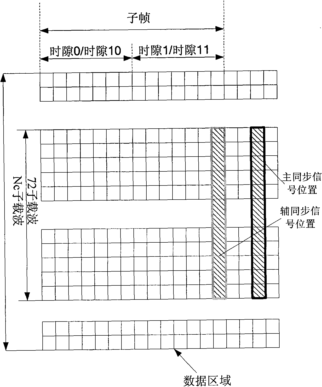
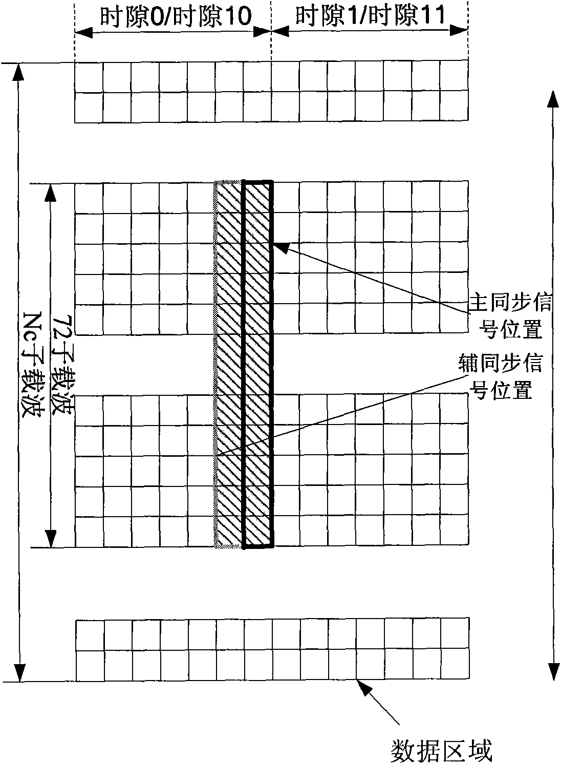
[0004] In addition, in the existing LTE system, the usual frequency offset estimation process includes two stages of frequency offset acquisition and frequency offset tracking. The current typical frequency offset acquisition technology uses the phase difference between the two segments before and after the primary synchronization signal to estimate. The frequency offset estimation range of offset capture is usually within 1 carrier interval, so due to the limitation of the number of sampling points and the requirement of frequency offset estimation range, the estimated acquisition accuracy is about 20% of the carrier interval
For the frequency offset tracking process, the prior art usually uses a reference signal (RS, ReferenceSignal) to do frequency estimation. Due to the design of the RS in the LTE system, the frequency estimation range in the frequency offset tracking process is usually about 14% of the carrier spacing. Therefore, the range of frequency offset estimation in the two stages of frequency offset acquisition and frequency offset tracking cannot be well connected, which in turn affects the demodulation performance of the link

Method used


Image

  • Method and device for capturing frequency deviation
  • Method and device for capturing frequency deviation
  • Method and device for capturing frequency deviation

Examples


Embodiment Construction

[0022] In order to make the object, technical solution and advantages of the present invention clearer, the present invention will be described in detail below with reference to the accompanying drawings and specific embodiments.

[0023] The method and device for capturing frequency offset according to the present invention can be applied to TDD (Time Division Duplexing, time division duplexing) mode and FDD (Frequency Division Duplexing, frequency division duplexing) mode in the 3GPP LTE system, and mainly utilize different OFDM symbols The channel estimation results of the primary synchronization signal and the secondary synchronization signal at the position are used for frequency offset acquisition. Compared with the method in the prior art that only uses the primary synchronization signal for frequency offset acquisition, the OFDM symbols used for frequency offset acquisition calculation in the present invention The number of sampling points is increased and the interval ...


PUM


Abstract

The present invention discloses a method and a device for capturing frequency deviation. The method is applied for the 3rd generation partnership project 3GPP Long Term Evolution 3GPP LTE system and comprises the following steps: executing time synchronization to the received signal sequence for confirming the position of synchronizing signal; obtaining the master synchronizing signal and auxiliary synchronizing signal of synchronizing signal in frequency domain; respectively executing channel estimation with the master synchronizing signal and auxiliary synchronizing signal for respectively obtaining the estimated values of time domain channel response at the positions of master synchronizing signal and auxiliary synchronizing signal; and calculating the frequency deviation with the phase difference between the estimated values of time domain channel response at the positions of master synchronizing signal and auxiliary synchronizing signal. The method and the device according to the invention can greatly increase the precision of prior frequency deviation capturing for satisfying the frequency deviation estimation range of frequency deviation tracking period thereby effectively increasing the demodulation performance of link circuit.

Description

technical field [0001] The present invention relates to the technical field of communication, in particular to a method applied to 3GPP LTE (The 3 rd A method and device for frequency offset acquisition in a Generation Partner Project Long term evolution (Generation Partner Project Long term evolution) system. Background technique [0002] With the development of society and the advancement of technology, people's requirements for mobile communication are constantly increasing, and it is hoped that the system can provide data transmission services with large capacity, high speed and low delay. In order to meet this growing demand. The 3GPP organization has proposed a long-term evolution plan (LTE) of the 3G system. The LTE system adopts the transmission technology of OFDM (Orthogonal Frequency Division Multiplexing, Orthogonal Frequency Division Multiplexing). Under the OFDM transmission technology, the system uses mutually orthogonal carriers, which improves the spectrum ...

Claims


Application Information

Patent Timeline
IPC IPC(8): H04B7/26H04L7/00
Inventor 翟海涛
Owner ST ERICSSON SEMICON BEIJING
Learn More