Knitting method of tubular fabric and weft knitting machine

A technology of tubular knitted fabric and flat knitting machine, which is applied in the direction of flat knitting machine, weft knitting and knitting with separate action needles to achieve the effect of improving knitting efficiency

Active Publication Date: 2011-09-14
SHIMA SEIKI MFG LTD
View PDF1 Cites 0 Cited by
  • Summary
  • Abstract
  • Description
  • Claims
  • Application Information

AI Technical Summary

Problems solved by technology

However, if both the knitting needles of the front and rear needle beds 4 are moved in and out of the tooth gap, interference will occur, so knitting such as flat knitting can be performed only with the knitting needles of one needle bed.

Method used


Image

  • Knitting method of tubular fabric and weft knitting machine
  • Knitting method of tubular fabric and weft knitting machine
  • Knitting method of tubular fabric and weft knitting machine

Examples


Embodiment Construction
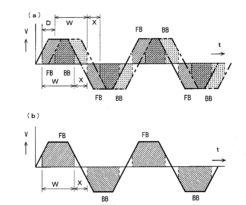
[0030] figure 1 The basic idea of ​​the knitting method of the tubular knitted fabric as an embodiment of the present invention is shown in comparison with the knitting method of the tubular knitted fabric woven by the conventional endless knitting. That is, in the present invention, as in figure 1 As shown in (a) as the change of the moving speed V with time t, in a flatbed knitting machine having a pair of needle beds such as the front needle bed FB and the rear needle bed BB, as indicated by the one-dot chain line and the two-dot chain line shows, weaving with a phase difference corresponding to the time difference D of weaving start Figure 9 (a) The tubular knitted fabric 11 as shown. The phase difference is provided so that the knitting needles performing the knitting operation moving in and out of the needle bed from the front and rear needle beds are spaced so that they do not interfere with each other. The position where the knitting needles are driven to carry o...


PUM


Abstract

A knitting method of a tubular fabric and a weft knitting machine in which knitting efficiency can be enhanced. As shown in (a) as a variation in moving speed (V) with time t, a tubular fabric intersecting at the opposite ends is knitted by a weft knitting machine having a pair of needle beds such as a front needle bed (FB) and a back needle bed (BB) while a phase difference is imparted as shown by a single dot chain line and a double dots chain line. The phase difference is provided in order to leave an interval for preventing interference of knitting needles advancing from the front and backneedle beds to the tip part and performing knitting operation. A position where an knitting operation is performed by driving the knitting needles changes depending on the position of a carriage reciprocating in the longitudinal direction of the needle bed while mounting a cam system. A fabric is knitted while being duplicated by means of the front and back needle beds (FB, BB) and a fabric substantially doubling that by the conventional circling knitting shown in (b) is knitted in a single stroke of the carriage, thus enhancing productivity.

Description

technical field [0001] The present invention relates to a knitting method and flat knitting machine for producing tubular knitted fabrics such as gloves in a seamless manner. Background technique [0002] in the past, Figure 8 As shown in (a), the tubular knitted fabric 1 is pressed as gloves, socks, etc. Figure 8 In the method shown in (b), knitting is carried out by a flat knitting machine equipped with a pair of needle beds at the front and rear. When knitting the tubular knitted fabric 1 , the knitting yarn 2 is circularly moved from the position where the yarn feeder 3 is supplied to the knitting needles to the front and rear needle beds. [0003] exist Figure 8 In (b), a straight line having a length corresponding to the knitting width knitting in the vicinity of the center of the opposing needle beds is marked with reference numeral 4, and the front and rear needle beds are simplified. On the front and rear needle beds 4, the carriages 5f, 5b are reciprocated in t...

Claims


Application Information

Patent Timeline
Patent Type & Authority Patents(China)
IPC IPC(8): D04B15/96D04B1/28D04B7/34A41D19/00
CPCD04B1/28D04B7/34D04B15/96
Inventor 池上隆
Owner SHIMA SEIKI MFG LTD
Why Eureka
Try Eureka