High-frequency pulse current transformer

A high-frequency pulse current and transformer technology, applied in the direction of inductors, voltage/current isolation, inductors with magnetic cores, etc., can solve the problems of high cost and complicated manufacturing process of current transformers, and achieve simple processing and low manufacturing cost Low, interference-reducing effect

Active Publication Date: 2009-10-14
桐庐恒英电子有限公司
View PDF0 Cites 6 Cited by
  • Summary
  • Abstract
  • Description
  • Claims
  • Application Information

AI Technical Summary

Problems solved by technology

[0005] The present invention mainly aims to solve the problems of complex manufacturing process and high cost of existing current transformers, and proposes a pulse current transformer with a simple structure, aiming at simplifying the manufacturing procedure and reducing the manufacturing cost

Method used


Image

  • High-frequency pulse current transformer
  • High-frequency pulse current transformer
  • High-frequency pulse current transformer

Examples


Embodiment Construction

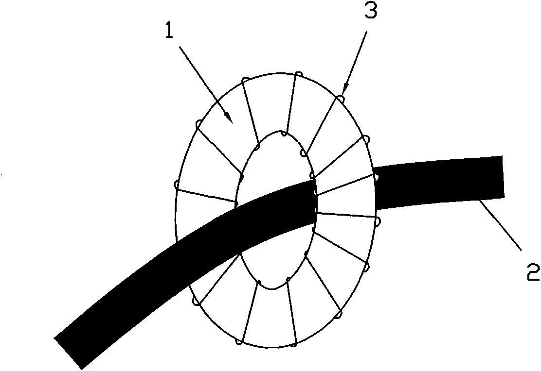
[0023] refer to figure 1 , the existing toroidal transformer, the magnetic core 1 is a closed annular structure, the signal winding 3 is wound on the toroidal magnetic core 1, and the sampled current signal 1 passes through the toroidal magnetic core 1, so that the signal winding 3 Obtain the required pulse current signal.

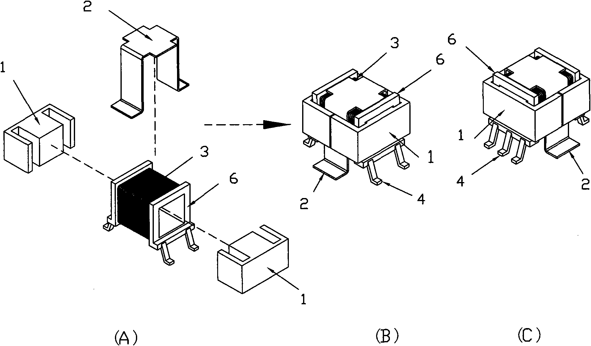
[0024] refer to figure 2 , is another existing pulse current transformer structure, including a pair of E-shaped magnetic cores 1 and a bobbin 6, the signal winding 3 is wound on the bobbin 6 first, and then processed into a metal conductive sheet of a specific shape 2 is placed on the winding 3, and then the coil bobbin 6 assembly is inserted into the center column of one of the E-shaped magnetic cores 1, and finally another E-shaped magnetic core 1 is inserted into the coil bobbin 6, and is connected with the first E-shaped magnetic core 1 Combine to form a closed magnetic circuit.

[0025] The above-mentioned defects in the prior art have been descr...


PUM


Abstract

The invention relates to a pulse current transformer used for switching power supply, which comprises one or a plurality of units which are basically identical. Each unit comprises an open circuit magnetic core and a closed magnetic circuit armature formed by being matched with the open circuit magnetic core. The pulse current transformer is characterized in that a winding is coiled on the magnetic core, a signal output pin is arranged on the magnetic core, and a metal conducting strip is arranged between the magnetic core and the armature. The signal winding is coiled on the open circuit magnetic core so as to faciliate the mechanical coiling, and then the armature is covered on the magnetic core to form a magnetic flux circuit, increase the inductance value of the transformer, reduce the leakage inductance, and reduce the interference of the external magnetic field to the transformer. The metal conducting strip is connected with the circuit of the sampled current, therefore, sampled current signals pass through the space between the magnetic core and the armature, current signals are induced on the winding, and the induced signals are output by the signal output pin. As no framework is required, the pulse current transformer is easy to be processed, and the production cost is low.

Description

technical field [0001] The invention relates to a pulse current transformer used in a switching power supply. Background technique [0002] High-frequency pulse current transformers are widely used in switching power supplies, and are generally used to detect switching frequency pulse currents as control, drive or protection signals. Commonly used pulse current transformers use toroidal cores or magnetic cores with skeletons, and the signal windings are wound on the magnetic rings or on the skeletons, and the sampled current signals pass through the magnetic rings or wind several turns on the skeletons. . In this way, the required pulse current signal can be obtained on the signal winding. [0003] Such an implementation method is relatively complicated, especially when a magnetic ring is used as a transformer. When the number of turns of the signal winding of the transformer reaches hundreds of turns, manual winding is required, and the cost is very high. When the bobbin...

Claims


Application Information

Patent Timeline
Patent Type & Authority Applications(China)
IPC IPC(8): H01F38/30H01F17/04G01R15/18H02M1/00
CPCH01F3/12H01F27/2866H01F38/30
Inventor 吴新科华桂潮黄逊
Owner 桐庐恒英电子有限公司
Why Eureka
Try Eureka