
Lubricating system, bearing utilizing the system, universal joint utilizing the system, and process for production thereof

A technology of universal joint and lubrication system, applied in the field of lubrication system, can solve the problems of difficulty, complicated operation, difficult assembly of parts with solid lubricant, etc., and achieve the effect of excellent running-in performance

Inactive Publication Date: 2009-10-14
NTN CORP
View PDF9 Cites 4 Cited by
  • Summary
  • Abstract
  • Description
  • Claims
  • Application Information

AI Technical Summary

Problems solved by technology

In addition, if the filling amount is too much, there is a problem that the solid lubricant becomes an obstacle and it is difficult to assemble parts.
In particular, when filling the internal space between the inner member and the outer member with solid lubricant, it is mainly necessary to fill the periphery of the torque transmission member such as the raceway and its raceway surface. Conversely, it is not necessary to fill the shaft hole of the inner member with solid lubricant. In order to fill only an appropriate amount of solid lubricant, it is necessary to adjust the pressure applied to the solid lubricant during filling and the amount of extrusion, and it is complicated and difficult to perform these operations reliably.

Method used


Image

  • Lubricating system, bearing utilizing the system, universal joint utilizing the system, and process for production thereof
  • Lubricating system, bearing utilizing the system, universal joint utilizing the system, and process for production thereof
  • Lubricating system, bearing utilizing the system, universal joint utilizing the system, and process for production thereof

Examples


Embodiment 1~ Embodiment 2

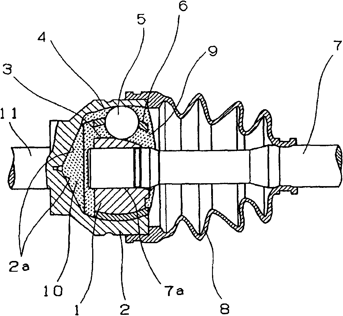
[0286] First, to figure 1 The bottom of the outer member shown, where eight fixed ball joint assemblies (EBJ82 manufactured by NTN Corporation, with an outer diameter of 72.6mm) assembled with the outer member 2, the inner member 1, the bearing cage 6 and the torque transmission member 5 , 5 g of initial lubrication grease shown in Table 1 was enclosed. Next, (a), (d), (e), and (i) in the composition shown in Table 1 were thoroughly mixed at 80°C, and (b) dissolved at 120°C was added and quickly mixed . Finally, (c) and (h) were thrown in and stirred, and then 15.0 g of the grease for initial lubrication was sealed in the joint. A few seconds later, the foaming reaction started, and it was placed in a constant temperature bath set at 100°C for 30 minutes to solidify, and other components such as a protective cover and a shaft were assembled to obtain a test piece of a constant velocity universal joint using a lubrication system. The obtained test piece was subjected to the ...

Embodiment 3~ Embodiment 4

[0300] First, in figure 1 The bottom of the outer member shown in the fixed 8-piece ball joint assembly (EBJ82 manufactured by NTN Co., Ltd. with an outer diameter of 72.6 mm) assembled with the outer member 2, the inner member 1, the bearing cage 6 and the torque transmission member 5 , 5 g of grease for initial lubrication shown in Table 1 was enclosed. A silicone-based foam stabilizer, mineral oil, an amine-based catalyst, and water as a foaming agent were added to the polyether polyol in the amount of components (composition) shown in Table 1, and heated at 90°C to fully stir. After adding isocyanate thereto and stirring well, 13.0 g of the above-mentioned joint which had already been sealed with grease for initial lubrication was sealed. After a few seconds, the foaming reaction started, and it was placed in a constant temperature bath set at 90°C for 15 minutes to solidify, and other components such as a protective cover and a shaft were assembled to obtain a test piece...

Embodiment 5~ Embodiment 6

[0312] First, in figure 1 Bottom of the outer member shown in the fixed 8-piece ball joint assembly (EBJ 82 manufactured by NTN Corporation with an outer diameter of 72.6mm) assembled with the outer member 2, the inner member 1, the bearing cage 6 and the torque transmission member 5 , 5 g of grease for initial lubrication shown in Table 2 was enclosed. Next, (a), (d), (e), and (i) in the composition shown in Table 2 were thoroughly mixed at 80°C, and then (b) dissolved at 120°C was added and quickly mixed. . Finally, (c) and (h) were thrown in and stirred, and then 15.0 g of the grease for initial lubrication was sealed in the joint. A few seconds later, the foaming reaction started, and it was placed in a constant temperature bath set at 100°C for 30 minutes to solidify, and other components such as a protective cover and a shaft were assembled to obtain a test piece of a constant velocity universal joint using a lubrication system. The same items as in Example 1 were mea...


PUM

PropertyMeasurementUnit
sizeaaaaaaaaaa
torqueaaaaaaaaaa

Abstract

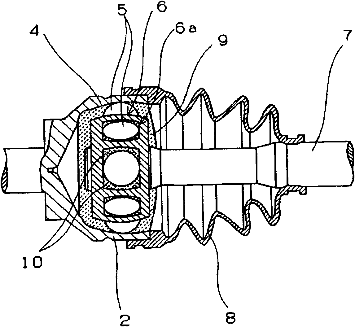
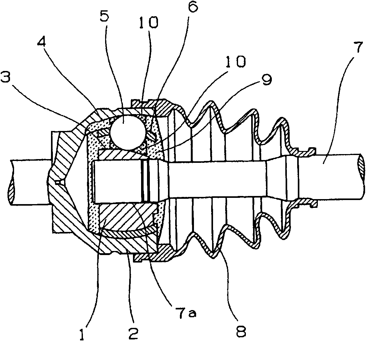
It is an object of the present invention to provide a lubricating system that improves the force of retaining a lubricating component of a foam lubricant, minimizes an exudation amount of the lubricating component caused by deformation of the foam lubricant, is excellent in initial lubrication, has a long life, has a low cost, and is excellent in the productivity thereof; a bearing utilizing the lubricating system; a universal joint utilizing the lubricating system; and a process for the production thereof. A lubricating system includes a foam lubricant (9) containing a lubricating component in a resin thereof which foams, hardens, and becomes porous and a lubricant (10) for initial lubrication which is present together with the foam lubricant (9) in a portion to be lubricated. The lubricant (10) for initial lubrication consists of grease having a worked penetration not less than 300 or having a degree of oil separation not less than 0.7 wt% when the grease is left 24 hours at 70 DEG C. or consists of lubricating oil having a kinematic viscosity not less than 50mm 2 / second at 40 DEG C.. In initial lubrication of the lubricating system, the lubricant (10) for initial lubrication is essentially present at a sliding portion of the portion to be lubricated.

Description

technical field [0001] The present invention relates to a lubrication system in which a foaming lubricant coexists with an initial lubricant as grease or lubricating oil, and which can supply lubricant to sliding parts of mechanical devices, etc., a bearing using the system, and a universal joint using the system and its production method. Background technique [0002] Generally, lubricants are used in sliding parts and rotating parts of bearings and the like used in most machines represented by automobiles and industrial machines. [0003] Usually, rolling bearings are filled with grease inside to lubricate the friction surfaces between the rolling elements and the inner and outer rings of the bearing and the cage, and sealing devices such as seals are provided so that the filled grease does not flow out to the outside and dust , moisture, etc. will not invade its interior. However, even in rolling bearings with seals, it is difficult to completely seal the grease. If use...

Claims


Application Information

Patent Timeline
Patent Type & Authority Applications(China)
IPC IPC(8): C10M171/00C10M149/14C10M149/20C10M177/00F16C33/66F16D3/20C10N20/00C10N20/02C10N30/00C10N30/06C10N40/02C10N40/04C10N50/08C10N50/10C10N70/00
Inventor 小原美香
Owner NTN CORP
Learn More