
Hydraulic coupler type coupling limited slip differential

A technology of hydraulic coupling and anti-slip differential, which is applied in the direction of differential transmission, belt/chain/gear, mechanical equipment, etc., and can solve the problems of unsuitable special road surface, complex operation and processing, and poor trafficability of vehicles and other issues, to achieve the effect of improving efficiency and flexibility, improving driving flexibility, and reducing costs

Inactive Publication Date: 2009-10-21
熊涔博
View PDF0 Cites 1 Cited by
  • Summary
  • Abstract
  • Description
  • Claims
  • Application Information

AI Technical Summary

Problems solved by technology

[0002] The ordinary gear differentials currently used in various automobiles cannot be applied to special road surfaces, that is, when one side of the wheel slips, the non-slipping wheel on the other side will not be able to obtain driving force and the car will not be able to move forward. Not good; for the existing various anti-skid differentials, the operation and processing are generally complicated, and it is easy to damage the half shaft due to excessive forced mechanical torque on a single half bearing, and the two half shafts cannot occur when the vehicle turns. Defects such as relative rotation that make the steering of the car difficult

Method used


Image

  • Hydraulic coupler type coupling limited slip differential
  • Hydraulic coupler type coupling limited slip differential

Examples


Embodiment Construction

[0014] The structure and function of the present invention will be described below in conjunction with the drawings

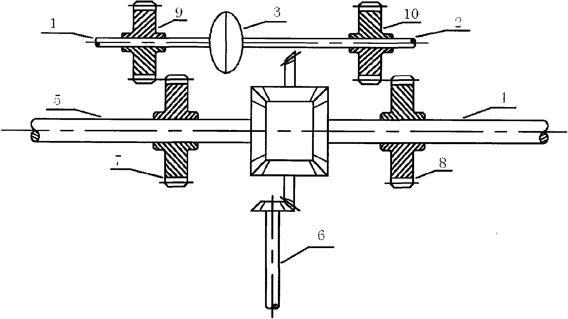
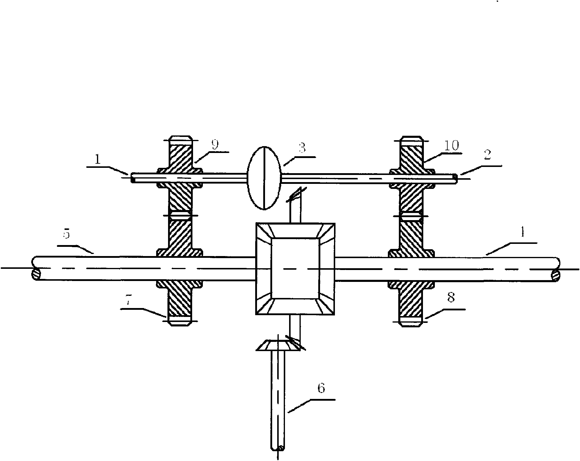
[0015] see figure 1 , the left half shaft of the vehicle axle (4), the right half shaft of the vehicle axle (5) and the power transmission shaft (6) constitute a common gear differential.

[0016] The right half shaft of the fluid coupling (1), the left half shaft of the fluid coupling (2) and the fluid coupling (3) constitute the coupling of the fluid coupling. When the two half shafts of the coupling are working The gears (9), (10) mesh with the gears (7), (8) on the axle shafts respectively for transmission.

[0017] The gears (9), (10) on the two semi-shafts of the coupling are disengaged from the gears (7) and (8) on the axle shafts respectively through the shifting device, and the differential works as a normal gear differential. to adapt to better road conditions.

[0018] Through the shifting device, the two half shafts of the coupling are respective...


PUM


Abstract

A hydraulic coupler type coupling limited slip differential comprises two shift functions: a common gear differential shift and a hydraulic coupler coupling differential shift. In the normal condition, the differential is at the common gear differential shift; in the better road conditions, the differential can bring high efficiency of the common gear differential to drive; in the poor road conditions, the shift can be changed, so that the differential is at the working state of the hydraulic coupler coupling differential drive, therefore, the driving shaft can automatically transmit more torques to a half-shaft with low rotation speed according to the rotation speed of two half-shafts at the transmission characteristic of the hydraulic coupler condition so as to drive the car and improve the trafficability characteristic.

Description

technical field [0001] The invention relates to an anti-skid differential, which is suitable for automobiles and other equipment. Background technique [0002] The ordinary gear differentials currently used in various automobiles cannot be applied to special road surfaces, that is, when one side of the wheel slips, the non-slipping wheel on the other side will not be able to obtain driving force and the car will not be able to move forward. Not good; for the existing various anti-skid differentials, the operation and processing are generally complicated, and it is easy to damage the half shaft due to excessive forced mechanical torque on a single half bearing, and the two half shafts cannot occur when the vehicle turns. Defects such as relative rotation that make the steering of the car difficult. [0003] Off-road vehicles, trucks and some passenger cars driving on poor road conditions have an even more urgent demand for high-performance limited slip differentials. Conte...

Claims


Application Information

Patent Timeline
Patent Type & Authority Applications(China)
IPC IPC(8): F16H48/12F16H48/18F16H48/20F16H48/26
Inventor 熊涔博
Owner 熊涔博
Learn More