Method for calibrating high-frequency electric field probe

A technology of high-frequency electric field and calibration method, applied in the fields of electromagnetic field characteristics, measurement of electrical variables, measurement devices, etc., can solve problems such as lack of calibration methods

Inactive Publication Date: 2009-10-21
STATE GRID ELECTRIC POWER RES INST
View PDF0 Cites 37 Cited by
  • Summary
  • Abstract
  • Description
  • Claims
  • Application Information

AI Technical Summary

Problems solved by technology

[0004] The purpose of the present invention is to transmit an electromagnetic field with a specific amplitude and specific frequency through a signal generating device in an anechoic chamber shielding electromagnetic fields, and at the same time place th

Method used


Image

  • Method for calibrating high-frequency electric field probe
  • Method for calibrating high-frequency electric field probe
  • Method for calibrating high-frequency electric field probe

Examples


Embodiment Construction

[0023] The present invention will be described in further detail below in conjunction with the accompanying drawings and embodiments, but these embodiments should not be construed as limiting the utility model.

[0024] The used test equipment of the present invention comprises:

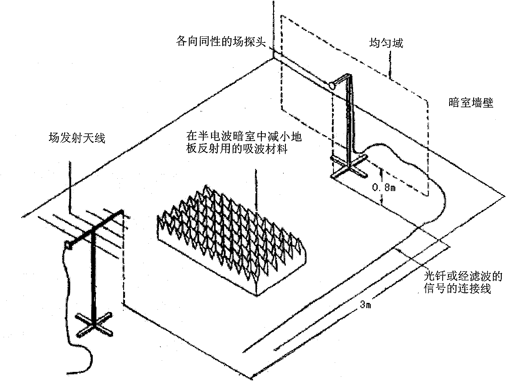
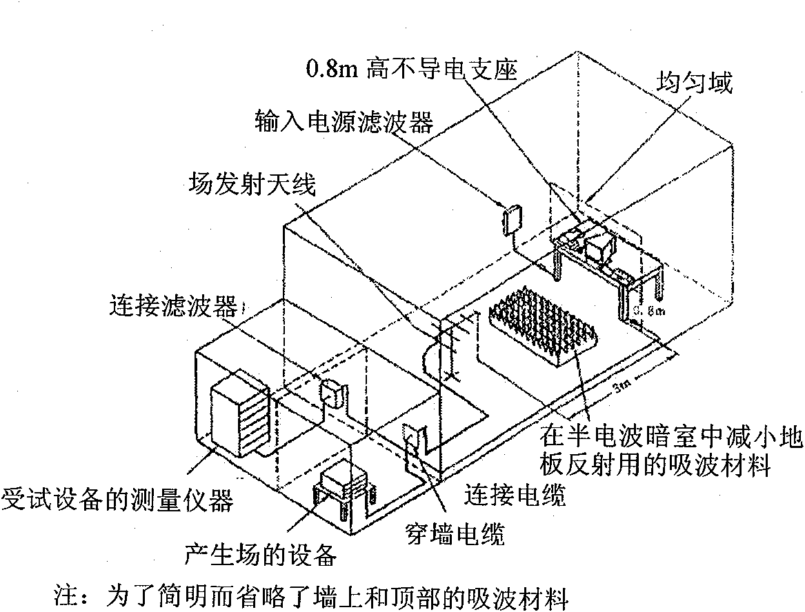
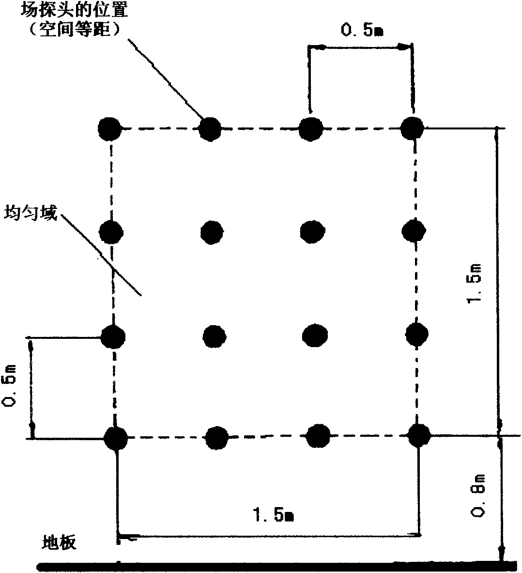
[0025] Anechoic chamber: It is of suitable size and can maintain a uniform field with sufficient space for the equipment under test (EUT). Partial installation of some absorbing materials can reduce the indoor reflection.

[0026] Electromagnetic Interference (EMI) Filters: Care should be taken to ensure that the filter does not cause resonance effects on the connecting lines

[0027] Radio frequency signal generator; Can cover all frequency bands of interest, and can carry out amplitude modulation by the sine wave of 1kHz, amplitude modulation depth 80%. should have to be slower than 1.5×10 -3 The automatic scan function of decade / s, if equipped with a frequency synthesizer, should have the progr...


PUM

PropertyMeasurementUnit
Total lengthaaaaaaaaaa

Abstract

The invention relates to a method for calibrating a high-frequency electric field probe, which comprises an anechoic chamber, an electromagnetic interference (EMI) filter, a radiofrequency signal generator, a power amplifier, a transmitting antenna, a vertical and horizontal polarization or isotropic field intensity monitoring antenna, and auxiliary equipment used for recording power level. The method comprises the following steps of: sending an electromagnetic field with specific amplitude and specific frequency through the radiofrequency signal generator in the anechoic chamber used for shielding an electromagnetic field, arranging a probe to be calibrated and the auxiliary equipment according to a certain mode, and realizing the calibration for the high-frequency electric field probe by comparing a produced field value and the reading of the electric field probe to be calibrated.

Description

technical field [0001] The invention belongs to the field of electromagnetic compatibility, in particular to a method for calibrating a small-sized high-frequency electric field probe. Background technique [0002] Electromagnetic radiation affects most electronic devices in some way. Such radiation is frequently produced by small hand-held transceivers such as those operated by maintenance and security personnel, fixed radio broadcasts, television station transmitters, vehicle-mounted radio transmitters, and various industrial electromagnetic sources. In addition to intentionally generated electromagnetic energy, there are also devices that generate stray radiation, such as electric welding machines, thyristor rectifiers, fluorescent lamps, switching operations of inductive loads, etc. This interference manifests itself as conducted interference in most cases. [0003] This kind of high-frequency electromagnetic field often exists in the living environment. With the enhan...

Claims


Application Information

Patent Timeline
IPC IPC(8): G01R35/00G01R29/08
Inventor 张广洲万保权邬雄蒋虹王勤张小武陈豫朝
Owner STATE GRID ELECTRIC POWER RES INST
Why Eureka
Try Eureka