
Life-saving casting device

A launcher and shoulder rest technology, applied in the field of life-saving equipment, can solve problems such as delay in inflation, no sealing, and separation, and achieve the effects of reducing the difficulty of rescue, shortening the interval time, and being easy to carry

Inactive Publication Date: 2009-10-28
黄山市齐云消防装备有限公司
View PDF2 Cites 6 Cited by
  • Summary
  • Abstract
  • Description
  • Claims
  • Application Information

AI Technical Summary

Problems solved by technology

The rescue throwing device of the prior art comprises a launcher seat, a gun handle, a shoulder rest, a sleeve pipe, a nozzle, a gun body connector, a launching gas cylinder, a life preserver, a lifeline, and an air pressure gauge, a pressure relief device, and a pressure gauge are installed on the launcher seat. Valve, air release valve, high-pressure connecting pipe, gun handle and safety pin, the shoulder rest is located at the rear of the launcher seat and is integrated with the launcher shell, and the gun body connector has a sealing ring groove and a core hole for high-pressure gas to pass through. The sealing ring is placed in the groove of the sealing ring. When it needs to be fired again, it is necessary to inflate the launch cylinder. Often because the gun body joint does not have a sealing ring, the seal fails and the inflation is delayed. The reason is the sealing ring of the gun body joint. Break away from the gun body when firing, and the rescuers forget to bring the sealing ring of the gun body connector before rushing to the scene of the emergency
The structure of the rescue thrower in the prior art is heavy and bulky, which is not convenient for rescuers to carry, and the scene of an emergency is often in a bad environment. When the rescuer cannot bring the rescue thrower to a suitable position for launching , which increases the difficulty of rescue of trapped persons

Method used


Image

  • Life-saving casting device
  • Life-saving casting device
  • Life-saving casting device

Examples


Embodiment Construction

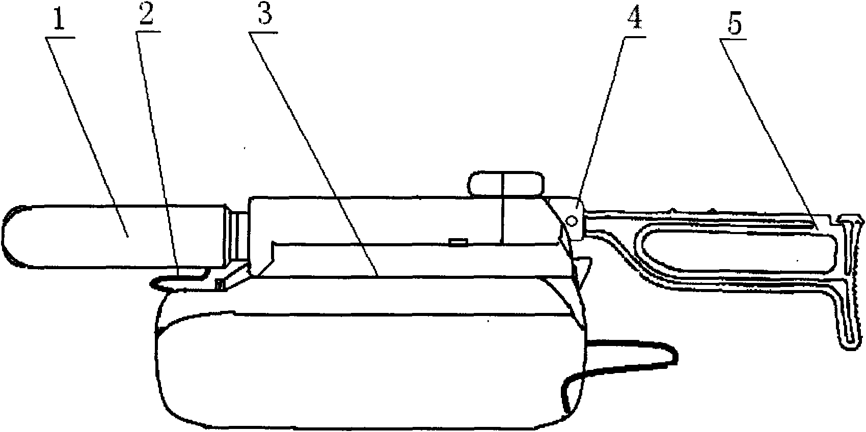
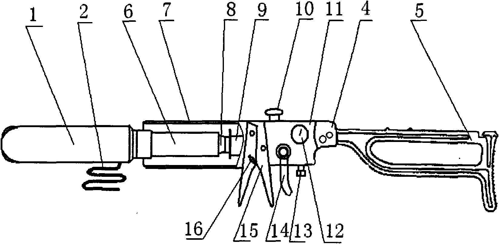
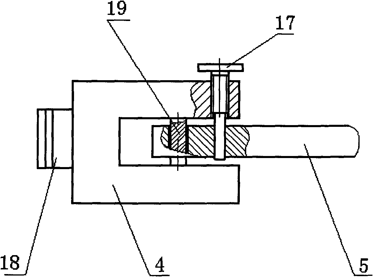
[0016] Such as figure 1 , figure 2 , image 3 , Figure 4 As shown, the rescue throwing device includes a launcher seat 11, a gun handle 15, a shoulder rest 5, a shoulder rest connection seat 4, a casing 7, a nozzle 8, a gun body connector 9, a launching gas cylinder 6, a life preserver 1, Lifeline 2 and textile knapsack 3, are equipped with air pressure gauge 12, pressure relief valve 13, deflation valve 10, high-pressure connecting pipe 14, gun handle 15 and safety pin 16 on launcher seat 11, and textile knapsack is divided into upper and lower two parts, The outer surface of the textile backpack is fixed with a buckle belt, the lifesaving rope 2 is placed in the lower cavity of the textile backpack 3, and the upper part of the textile backpack 3 has fasteners containing the launcher seat 11, the gun handle and the casing 7 , between the tail end of the transmitter seat 11 and the shoulder rest 5, there is a shoulder rest connecting seat 4 that is engaged with each other...


PUM


Abstract

The invention discloses a life-saving casting device, comprising an ejector seat, a gun handle, a shouldering, a sleeve, a nozzle, a gun body joint, an ejection air bottle, a life-saving cylinder, and a life-saving rope. The life-saving rope is disposed in the lower cavity of the textile backpack. A fastening piece accommodating the ejector seat, the gun handle and the sleeve is provided in the upper portion of the textile backpack. A detachable shouldering connecting seat is disposed between the tail end of the ejector seat and the shouldering, which is in U-shape, having one end rotatably connected to a pin shaft disposed in the concave slot of the shouldering connecting seat. The axis of the pin roll is perpendicular to the central line, and positioning piece of the fixed shouldering is disposed on the shouldering connecting seat. By adopting such a manner, the life saving casting device is compact in size, light in weight, as a result carrying by rescue worker to an appropriate location in emergency field for ejection is facilitated, which is beneficial to holding best life-saving opportunity by the rescue worker, and difficulty of rescuing the trapped is lowered.

Description

technical field [0001] The invention relates to a lifesaving appliance, in particular to a rescue thrower. Background technique [0002] At the scene of emergencies such as flood fighting and disaster relief, mountain torrents, huge waves at sea, and ship distress, when the trapped people need rescue at a critical moment and the rescuers cannot get close to the trapped people, ordinary life buoys are difficult to give to the trapped people. Even if the trapped people get a life buoy, it is difficult for the trapped people to turn the crisis to safety due to the harsh environment of strong winds, big waves and rapids, and the rescuers may lose the best time to rescue, causing the trapped people to fall into the water or die from cold and hunger. Chinese Patent Publication No. CN101021398A discloses a rescue throwing device; Chinese Patent No. 200420024242.6 discloses a lifesaving throwing device, which can overcome the shortcomings of ordinary lifebuoys and improve lifesaving...

Claims


Application Information

Patent Timeline
Patent Type & Authority Applications(China)
IPC IPC(8): B63C9/26F41B11/06F41B11/34F41B11/62F41B11/73
Inventor 严本元郑春生朱江河
Owner 黄山市齐云消防装备有限公司
Learn More