DC motor and generator
A technology of generators and planetary gears, which is applied in the direction of electric components, transmissions, mechanical equipment, etc., can solve the problems of dispersion and consumption of the torque of the rotating shaft of the motor rotor, and achieve the effect of saving space
- Summary
- Abstract
- Description
- Claims
- Application Information
AI Technical Summary
Problems solved by technology
Method used
Image

Examples
Embodiment 1
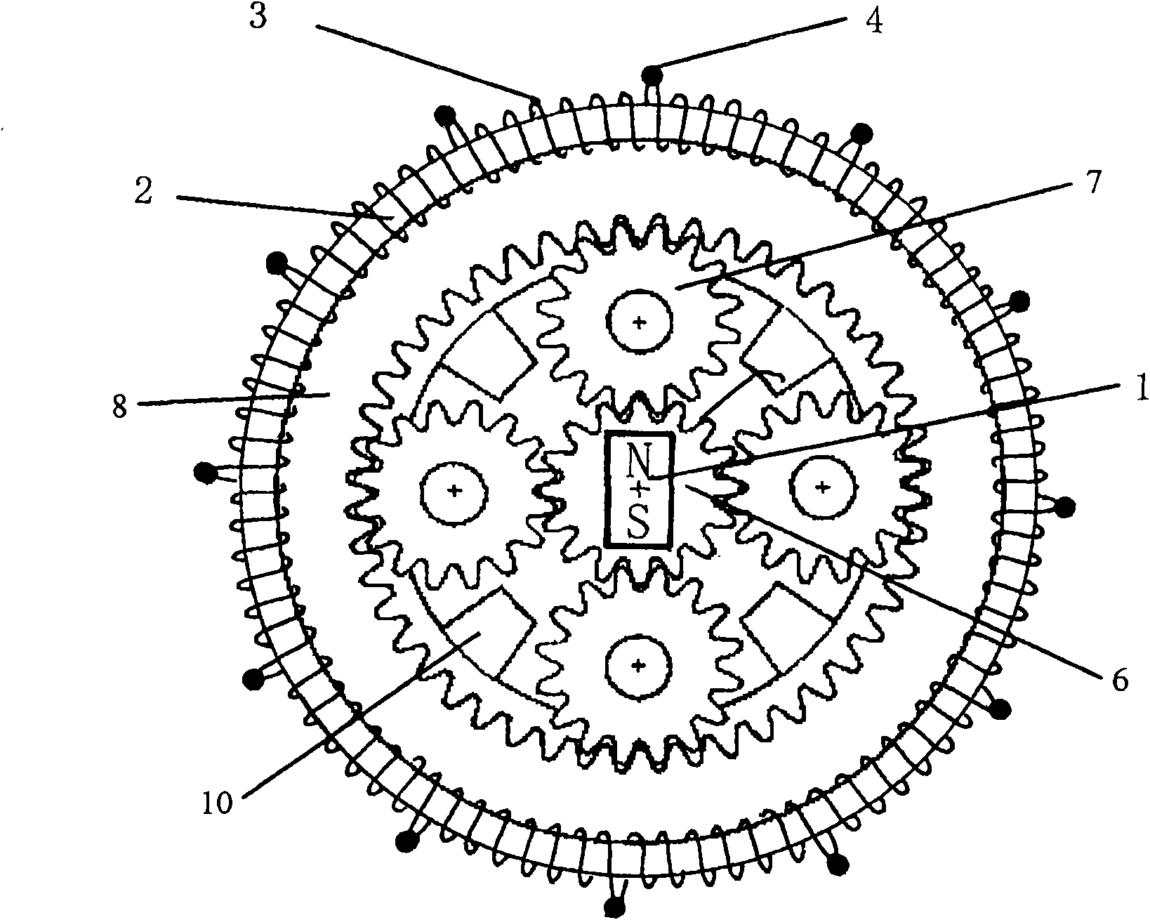
[0096] image 3 It is the front view of the planetary gear motor of the present invention. The permanent magnets of the two-pole inner magnet rotor 1 of the present invention are integrally provided on the sun gear 6 , and the four planetary gears 7 are held so as to mesh with the sun gear 6 . The number of planetary gears is just an example. The planetary gear 7 is rotatably held by the carrier 10 , and is held rotatably by the meshing of the internal gear 8 and the planetary gear 7 . As an example, 12 toroidal coils 3 are neatly wound around the seamless toroidal core 2 on the outer periphery of the internal gear 11, and 12 input terminals 4 are provided. The method of generating the rotational force of the sun gear 6 is the same as that of the two-pole DC motor of the present invention.
[0097] Figure 4 It is a side sectional view of the planetary gear motor of the present invention. As can be seen from this cross-sectional view, the sun gear 6, the planetary gear 7,...
Embodiment 2
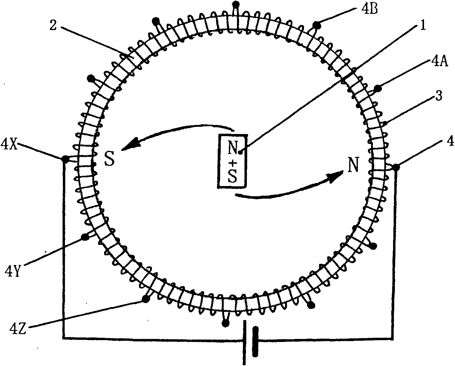
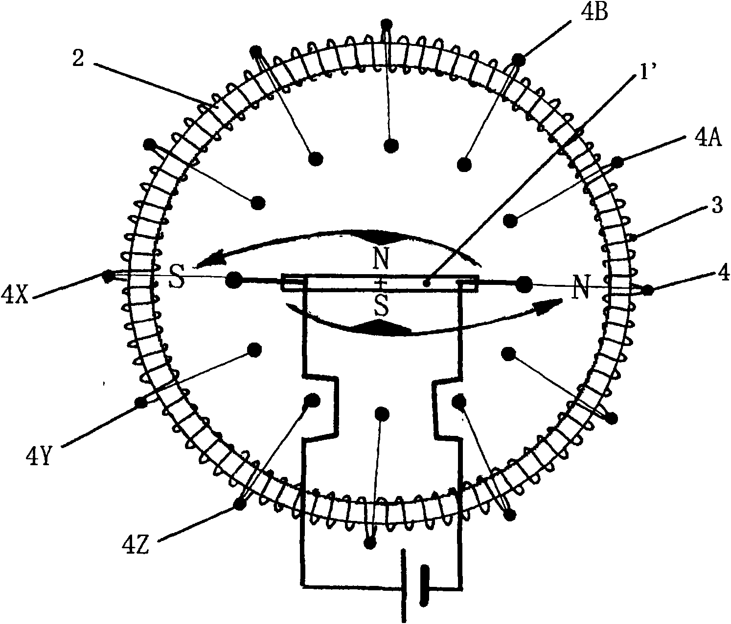
[0099] Image 6 It is shown that the ratio of the rotation diameter of the front end of the magnetic pole of the two-pole inner magnet rotor 1 of the present invention to the inner diameter of the annular iron core 2 conforms to the golden section ratio, that is, 61.80339%, which is based on the inner diameter of the annular iron core 2 and the two poles. The ratio of the magnetic attraction force between the magnet rotor 1 and the influence of the rotational torque is measured and derived from the result. Figure 7 Shown is a two-pole inner magnet rotor 1' of a plate magnet magnetic field arranged according to the rotation diameter of the above-mentioned golden ratio.
[0100] Two-pole inner magnet rotor 1 and two-pole inner magnet rotor 1' with Figure 5 and Figure 8 Compared with the two-pole internal magnet rotor 1', the shown two-pole internal magnet rotor 1 has a larger torque and a slower rotation speed, so it is suitable for low speed and high torque.
[0101] As a...
Embodiment 3
[0106] Figure 11 and Figure 12 For the two-pole inner magnet rotor 1 of the strip magnet magnetic field and the two-pole inner magnet rotor 1' of the plate magnet magnetic field are arranged on the figure deviated from the armature center 5 of the seamless annular iron core 2.
[0107] In the above-mentioned figures, the gap between the annular iron core 2 and the two-pole internal magnet rotor 1 or the two-pole internal magnet rotor 1' deviates as the feature of the present invention, and mechanical devices such as gears formed of non-magnetic materials can also be provided at the armature center 5.
[0108] As an example, a two-pole DC motor of the present invention is formed in the following manner, that is, having Figure 11 The rotating diameter of the two-pole internal magnet rotor 1 of the bar magnet type magnetic field shown is formed to be 33 mm, and 12 holes are evenly provided on the entire circumference of the annular iron core 2 with an inner diameter of 130 mm...
PUM
 Abstract
Description
Claims
Application Information
 - R&D
- Intellectual Property
- Life Sciences
- Materials
- Tech Scout
- Unparalleled Data Quality
- Higher Quality Content
- 60% Fewer Hallucinations
Browse by: Latest US Patents, China's latest patents, Technical Efficacy Thesaurus, Application Domain, Technology Topic, Popular Technical Reports.
© 2025 PatSnap. All rights reserved.Legal|Privacy policy|Modern Slavery Act Transparency Statement|Sitemap|About US| Contact US: help@patsnap.com