Containment sump filter

A containment pit and filter technology, which is applied in the field of safety systems, can solve problems such as insufficient filtration area, limited number, and insufficient filtration area to achieve the effect of increasing the filtration area and reducing the risk of clogging

Active Publication Date: 2009-11-04
CHINA GENERAL NUCLEAR POWER CORP +1
View PDF0 Cites 29 Cited by
  • Summary
  • Abstract
  • Description
  • Claims
  • Application Information

AI Technical Summary

Problems solved by technology

However, there are certain problems in this arrangement. For the pump inlets 106 and 108, due to their relatively close positions, only a small number of concentric tubular filter modules 9' can be arranged between them, resulting in the filtration of the two pump inlets 106 and 108. The area is not enough, and the amount of coolant entering the two pump inlets 106 and 108 will be much smaller than the amount of coolant entering the other two pump inlets 104 and 110
As for the pump inlet 110 on the right side, since there is an elevator entrance on the right side of the containment pit of the PWR nuclear power plant, the number of concentric tubular filter modules 9' that can be arranged between the pump inlet 110 and the elevator entrance is also limited. , which may also cause insufficient filter area
And also due to the limited number of concentric tubular filter modules 9' connected to the pump inlets 106 and 108, once these concentric tubular filter modules 9' are blocked, the water intake of the pump inlets 106 and 108 will be directly affected , thereby affecting the normal operation of the safety injection system and the containment spray system

Method used


Image

  • Containment sump filter
  • Containment sump filter
  • Containment sump filter

Examples


Embodiment Construction

[0023] In order to make the object, technical solution and advantages of the present invention clearer, the present invention will be further described in detail below in conjunction with the accompanying drawings.

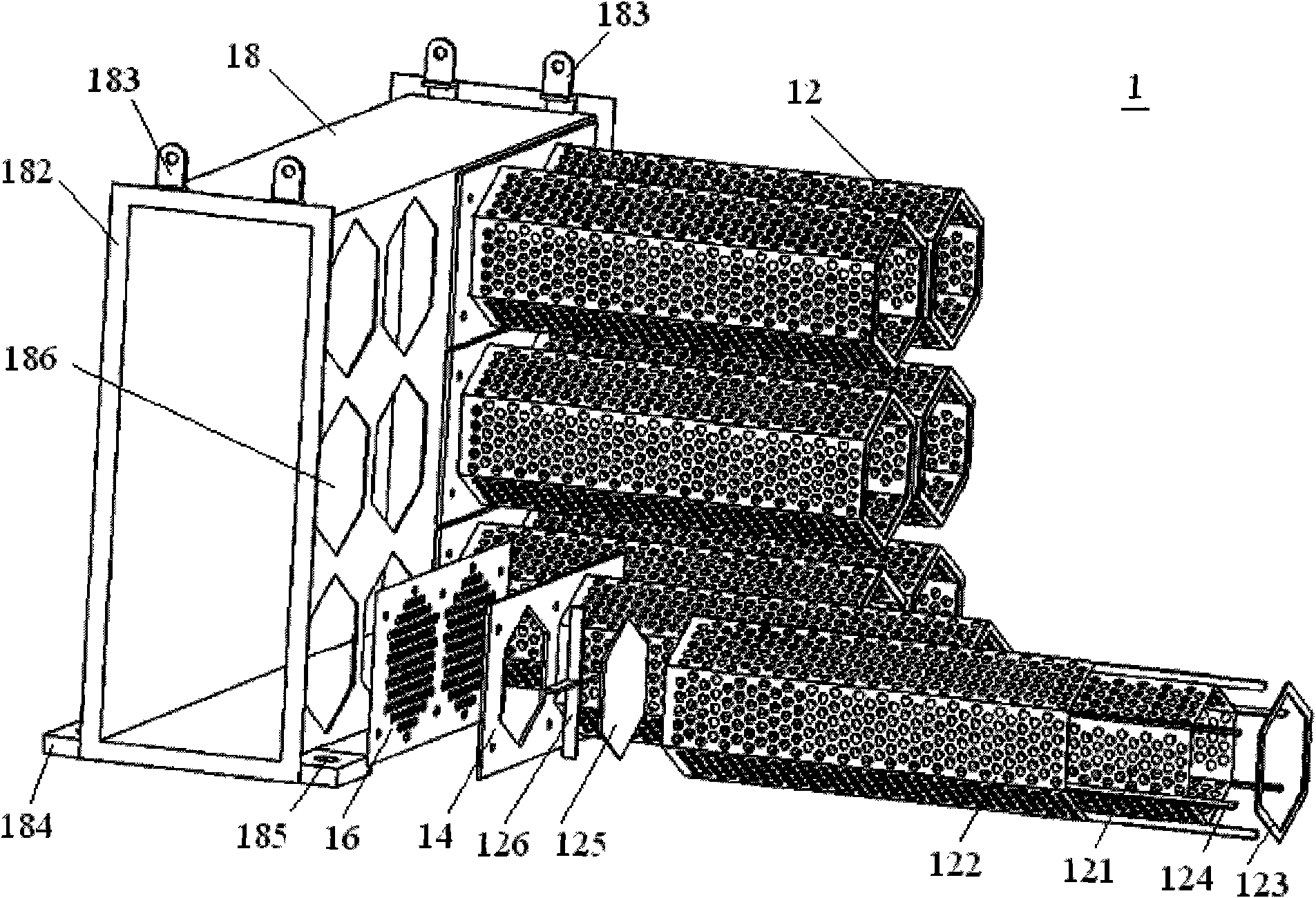
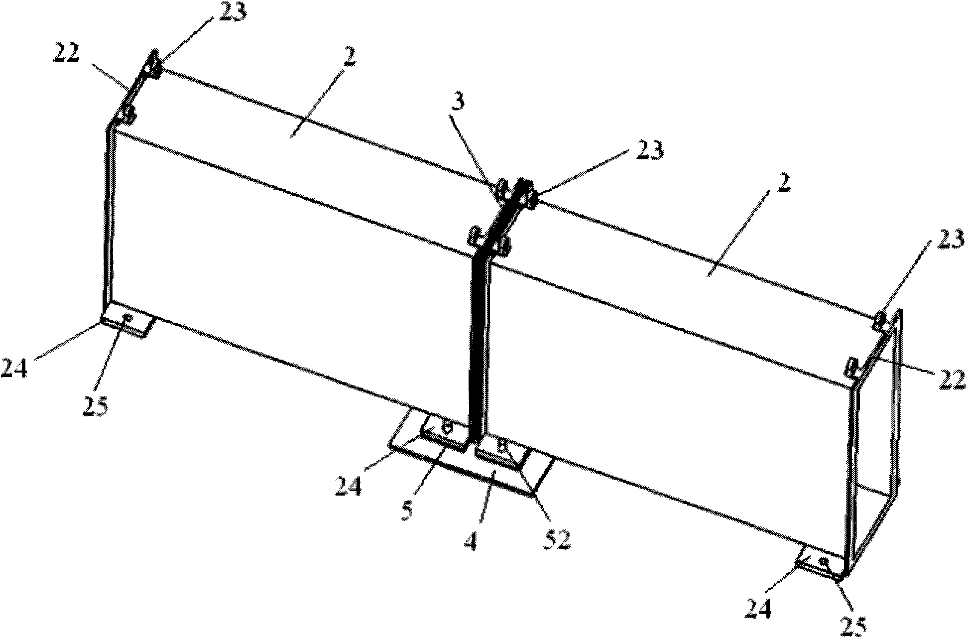
[0024] Please refer to figure 1 As shown, the containment pit filter of the embodiment of the present invention is assembled from a plurality of filter modules 1 , a plurality of pipeline modules 2 and a plurality of sealing assemblies 3 .

[0025] The structure of the filter module 1 is substantially the same, including a plurality of filter cartridges 12 , a fixing plate 14 , a filter plate 16 and a base 18 .

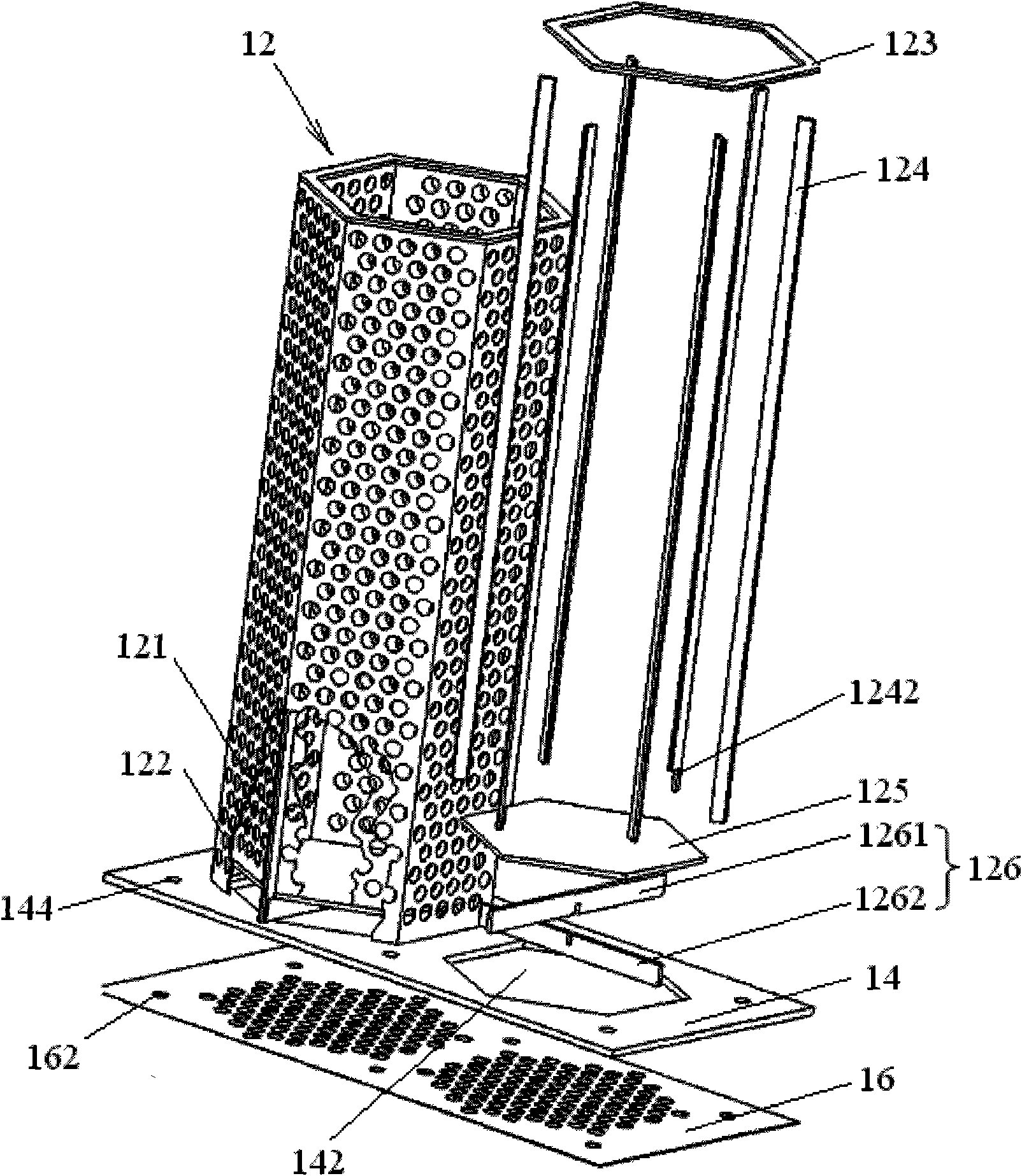
[0026] Please refer to figure 2 As shown, the filter cartridge 12 is roughly cylindrical, and includes an inner filter 121 , an outer filter 122 , a top plate 123 , ribs 124 , a bottom plate 125 , and a support plate 126 .

[0027] Both the inner filter net 121 and the outer filter net 122 are cylinders with a regular hexagonal cross-section formed by...


PUM


Abstract

The embodiment of the invention discloses a containment sump filter, comprising a plurality of filter modules which comprise a filter cartridge and a base; the invention is characterized in that: the containment sump filter also comprises a plurality of pipeline modules, the two ends of each pipeline are open, the pipeline modules forms a pipeline part by being connected with each other in an end-to-end way, the pipeline part is communicated with a plurality of pump inlets in the containment vessel pit and the two ends thereof are respectively connected with a plurality of filter modules which are connected with each other by the bases in an end-to-end way, so that the fluid passage formed by the bases of the filter modules at the two ends of the pipeline part can be communicated with the fluid of the pipeline part formed by the pipeline module. With the containment sump filter of the embodiment adopted, the filtration area in the flow passage of the refrigerant is increased remarkably without being restricted by the inlet location of the pump in the containment sump filter and at the same time, the risk of jam of the containment sump filter Is reduced.

Description

technical field [0001] The invention relates to a safety system of a pressurized water reactor nuclear power plant, in particular to a containment pit filter used in a pressurized water reactor nuclear power plant. Background technique [0002] The pit located at the bottom of the containment vessel of the pressurized water reactor nuclear power plant is used to collect the coolant from the primary circuit in case of major leakage. After a basic accident such as a loss of coolant accident (LOCA) or a main steam line rupture accident (MSLB) in a pressurized water reactor nuclear power plant, the coolant enters the containment pit through the breach, and the coolant will be filtered through the containment pit filter , and then enter the Safety Injection System (RIS) and the Containment Spray System (EAS) through the pump device, and then used for reactor cooling to avoid serious damage to the core and overpressure of the containment vessel. [0003] Therefore, the containmen...

Claims


Application Information

Patent Timeline
Patent Type & Authority Applications(China)
IPC IPC(8): B01D35/02B01D29/50B01D36/00G21C15/00G21C9/00
CPCY02E30/40Y02E30/30
Inventor 张臣刚向文元姚振农高咏杨刘青松
Owner CHINA GENERAL NUCLEAR POWER CORP
Why Eureka
Try Eureka