

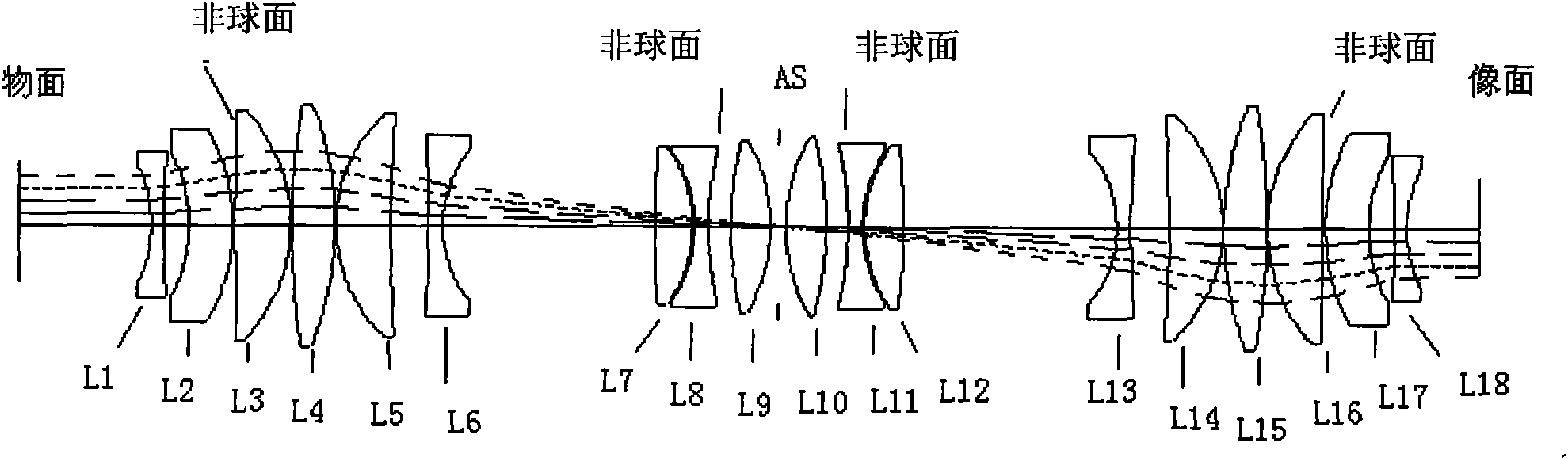
Low thermal effect projection objective
A technology of projection objective lens and thermal effect, which is applied in the field of optical systems, can solve the problems of impact, low thermal conductivity of optical materials, convection and density changes of the surrounding air medium, and does not consider the elimination of lens and lens holder stress, etc., so as to reduce adverse effects Effect
- Summary
- Abstract
- Description
- Claims
- Application Information
AI Technical Summary
Problems solved by technology
Method used
Image

Examples
Embodiment Construction
[0024] The thermal effect characteristics of the lens are characterized by the lens life / thermal effect sensitivity coefficient:
[0025] K LT / LH = D D > ( CA > CA ) 2 Formula 1
[0026] Among them, D represents the thickness of a single lens, CA represents the effective aperture of a single lens, Indicates the average central thickness of N lenses, Indicates the average light aperture of N lenses.
[0027] Projection objective lens according to the present invention is by thermal effect sensitivity coefficient K LT / LH Different lens composition.
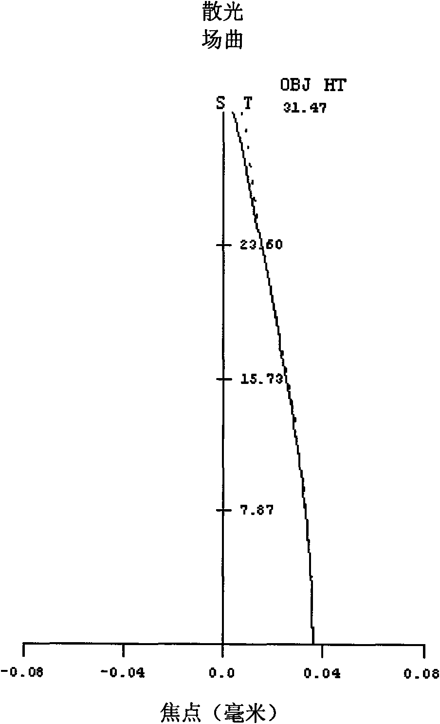
[0028] The image quality change caused by thermal effects is mainly reflec...
PUM
 Abstract
Description
Claims
Application Information