Zoom lens system and imaging apparatus

一种变焦透镜、透镜组的技术,应用在图像通信、电视、光学等方向,能够解决距离变大、透镜外径扩大、第3透镜组移动量变大等问题,达到良好摄像性能的效果

Inactive Publication Date: 2009-11-04
FUJI PHOTO OPTICAL CO LTD
View PDF4 Cites 6 Cited by
  • Summary
  • Abstract
  • Description
  • Claims
  • Application Information

AI Technical Summary

Problems solved by technology

[0008] However, the zoom lens described in Patent Document 1 is a system in which the diaphragm and the adjacent lens group move independently when changing magnification, but the moving distance of the diaphragm when changing magnification is relatively large relative to the image plane, so the diaphragm moving mechanism becomes long. difficult to miniaturize
In addition, the focal length of the first lens group is relatively long, so the total length of the lens is also long, making it difficult to downsize
[0009] Furthermore, the zoom lens described in Patent Document 3 is a method in which the diaphragm moves together with the third lens group when changing magnification, but the focal length of the third lens group is equal to that of the fourth lens group, so the third lens group has the same focal length when changing magnification. The amount of movement becomes large and it is difficult to miniaturize
In addition, the focal length of the first lens group is relatively long, so the total length of the lens is also long and it is difficult to miniaturize
[0010] In addition, the zoom lenses described in Patent Documents 2 and 4 are of a type in which the diaphragm moves toward the image side at the telephoto end rather than at the wide-angle end when changing magnification, so the distance between the first lens group and the diaphragm becomes larger when telephoto, and the first The outer diameter of the lens of the lens group increases and it is difficult to miniaturize

Method used


Image

  • Zoom lens system and imaging apparatus
  • Zoom lens system and imaging apparatus
  • Zoom lens system and imaging apparatus

Examples


Embodiment 1

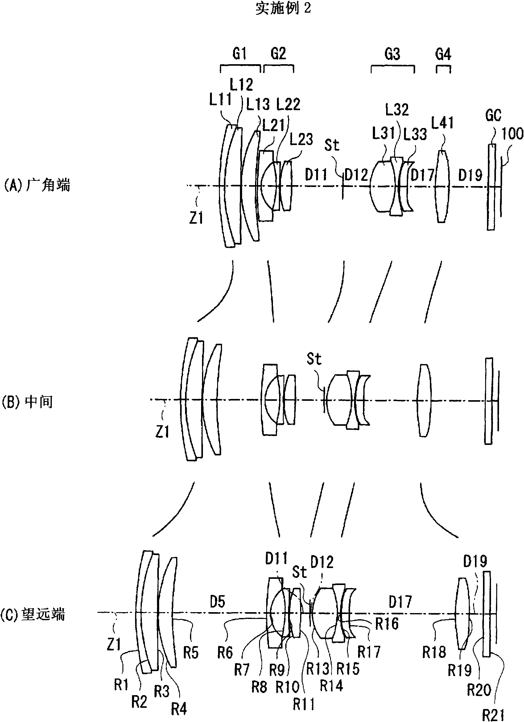
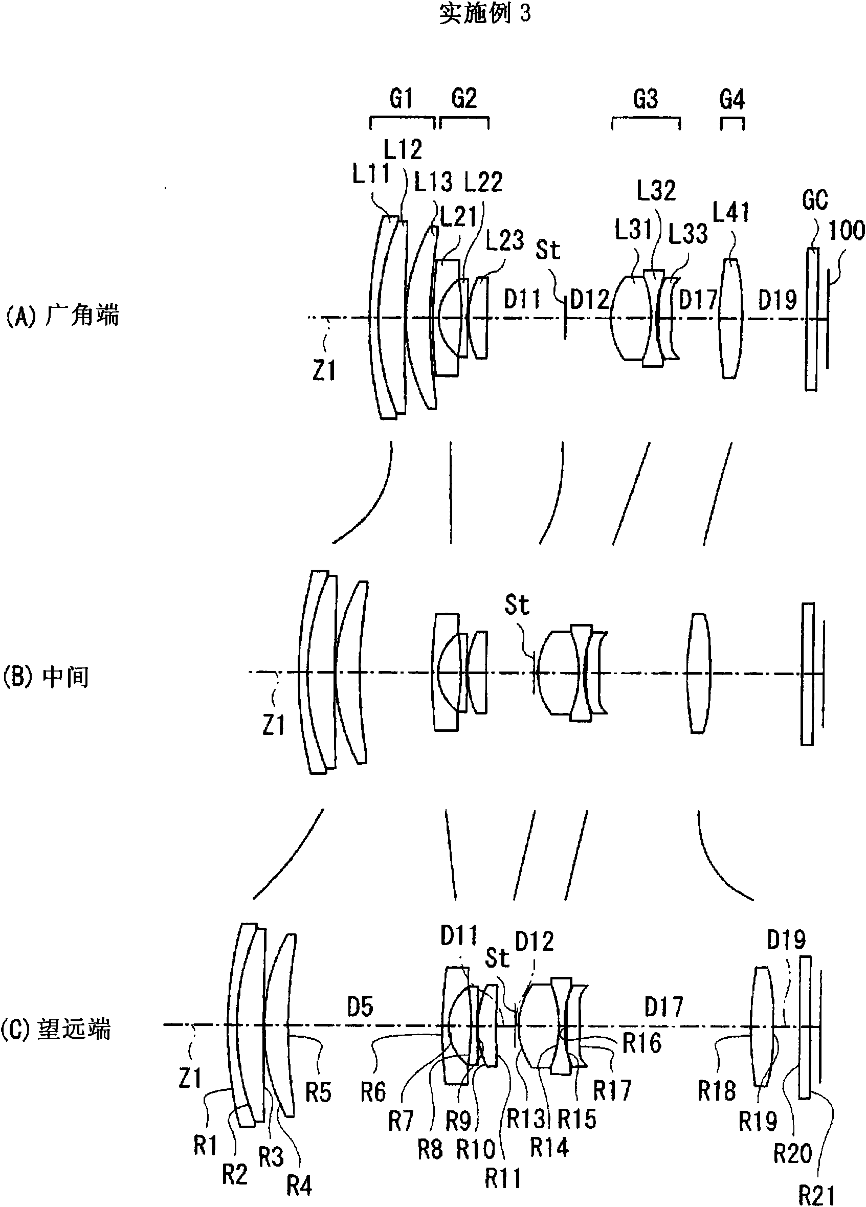
[0090] In the zoom lens of Embodiment 1, the aperture stop St and each lens group move on the optical axis as the magnification is changed, so the values ​​of the front-to-back distances D5, D11, D12, D17, and D19 between the aperture stop St and each lens group can be changed. Change. exist Figure 5 (B) shows the values ​​at the wide-angle end, the intermediate end, and the telephoto end as data at the time of zooming in on these plane intervals D5 , D11 , D12 , D17 , and D19 .

[0091] exist Figure 5 In the lens data of (A), the mark "*" attached to the left side of the surface number indicates that the lens surface has an aspherical shape. In the zoom lens of Example 1, both surfaces S16 and S17 of the single lens L33 in the third lens group G3 and both surfaces S18 and S19 of the positive lens L41 in the fourth lens group G4 are all aspherical. Figure 5 The basic lens data in (A) shows the numerical value of the radius of curvature near the optical axis as the radius...


PUM


Abstract

A positive first lens group G1, a negative second lens group G2, an aperture diaphragm St, a positive third lens group G3, and a positive fourth lens group G4 are sequentially arranged, and a movement of the lens groups and the aperture diaphragm St during zooming is optimized in combination with an appropriate conditional expression. During zooming, a position of the aperture diaphragm St on an optical axis at a wide-angle end is closer to an image plane than that at a telephoto end, and a space on the optical axis at the wide-angle end between the aperture diaphragm St and the third lens group G3 is larger than that at the telephoto end, thereby suppressing the length of the whole lens. Also, heights of rays passing through the first lens group G1 are lowered, thereby suppressing the lens diameter of the first lens group G1. The following conditional expression is satisfied: 0.4<(Pt-Pw) / fw<0.9 (1), where fw denotes a focal length of the whole system at the wide-angle end, Pw denotes a distance on the optical axis at the wide-angle end between the image plane and the stop, and Pt denotes a distance on the optical axis at the telephoto end between the image plane and the stop, thereby realizing a high variable power ratio and a small size as a whole.

Description

technical field [0001] The present invention relates to a zoom lens and an imaging device suitable for use in video cameras, digital still cameras, and personal digital assistance terminals (PDA: Personal Digital Assistance). Background technique [0002] In recent years, in imaging devices such as digital still cameras, miniaturization of the entire device has been demanded along with miniaturization of imaging elements such as CCD (Charge Coupled Device) and CMOS (Complementary Metal Oxide Semiconductor). In order to achieve miniaturization of the imaging device as a whole, it is also preferable to miniaturize the entire lens system (reduction in total length of the lens and miniaturization of the outer diameter of the lens). [0003] Patent Documents 1 to 4 disclose four-group zoom lenses in which four lens groups having positive, negative, positive, and positive refractive powers are sequentially arranged from the object side. In the zoom lenses described in these docum...

Claims


Application Information

Patent Timeline
Patent Type & Authority Applications(China)
IPC IPC(8): G02B15/177G02B13/00G02B13/18H04N5/225
CPCG02B15/173G02B15/144113
Inventor 小里哲也
Owner FUJI PHOTO OPTICAL CO LTD
Why Eureka
Try Eureka