Molding machine

A forming machine and hot-press forming technology, applied in the direction of electrical components, circuits, conductor/cable insulation, etc., can solve the problem of reducing the alignment accuracy of the opening and the bonding accuracy of the reinforcing plate, which is not conducive to the production of short-term special models, and improves the adjustment Problems such as machine difficulty and manufacturing cost can be solved to achieve the effects of reducing the walking range, improving production stability, and improving stability and accuracy.

Active Publication Date: 2009-11-04
SHENZHEN WENXIN ELECTRONICS
View PDF0 Cites 13 Cited by
  • Summary
  • Abstract
  • Description
  • Claims
  • Application Information

AI Technical Summary

Problems solved by technology

Although the Japanese SAIYIKAWA equipment mentioned above can complete the two actions of punching and pasting and reinforcement before heat pressing, it reduces the opening alignment accuracy and the bonding accuracy of the reinforcing plate during product production, and there is no automatic tracking The system makes the slitting accuracy impossible to guarantee. At the same time, the equipment is not conducive to the production of short-term production and special model products, and the stability of the production process is not high.
Although the Korean ATK equipment separates the punching and reinforcement actions through two presses, the design before the first press is complicated and the process is long, which increases the difficulty of machine adjustment and manufacturing costs. The accuracy of opening alignment is also unstable when improving processing. At the same time, the low-precision photoelectric automatic tracking system can only control the slitting accuracy within the range of 0.02, resulting in low work efficiency and high defect rate of products.

Method used


Image

  • Molding machine
  • Molding machine
  • Molding machine

Examples


Embodiment Construction

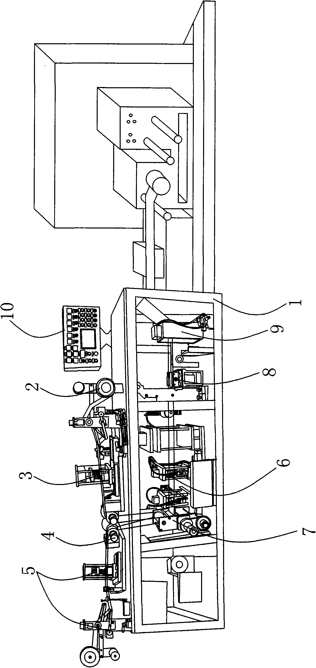
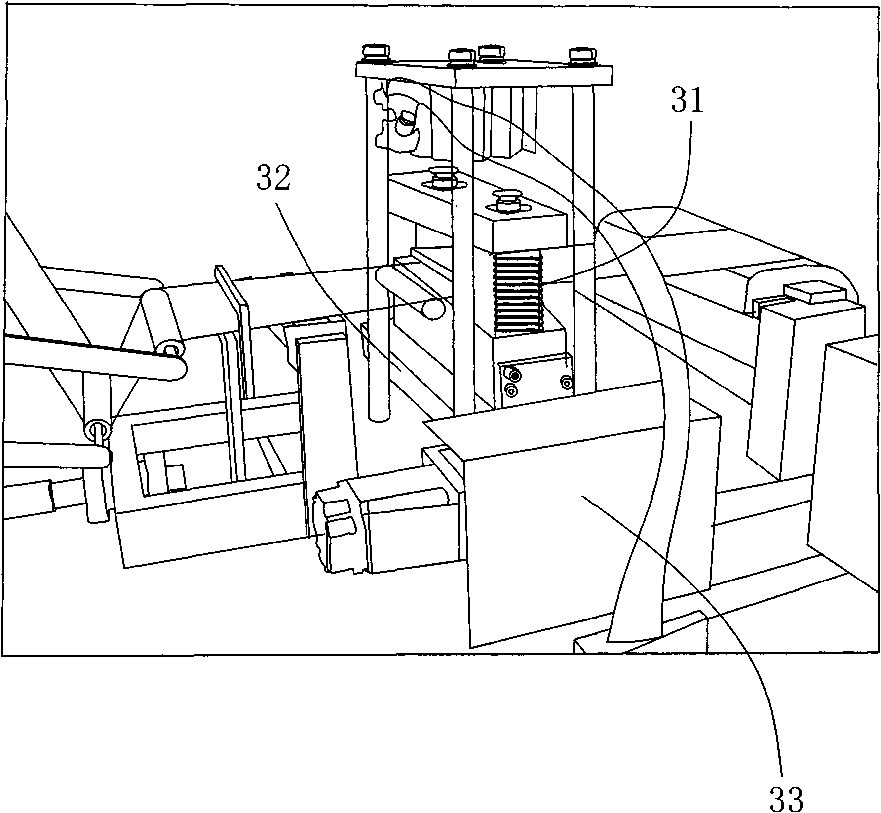
[0025] Please refer to Figure 1 to Figure 8 As shown, a molding machine provided in the present invention will be described below in conjunction with a specific embodiment, which includes a frame 1, an adhesive film supply device 2, an adhesive film opening device 3, a primary molded body 4, and a flat-angle copper wire arrangement device 5. Hot pressing forming device 7, reinforcing plate laminating device 6, secondary forming body, slitting device 8, traction device 9, electric control panel structure 10 and wire take-up device.

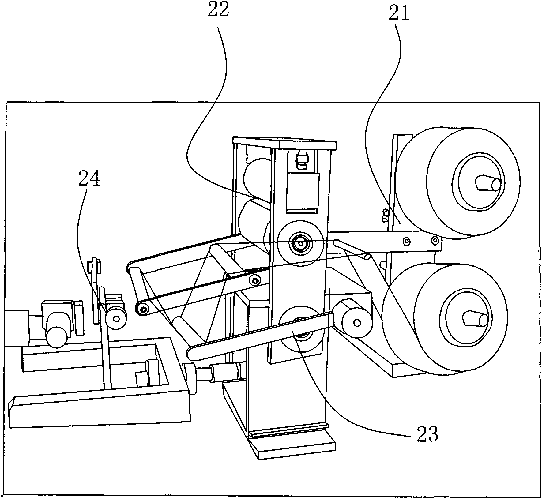
[0026] The film supply device 2 includes a material rack 21, a feeding mechanism 22 arranged on one side of the material rack 21, a tension and speed adjustment mechanism 23 arranged at the bottom of the feeding mechanism 22, and a deviation correcting device 24 arranged on one side of the feeding mechanism 22 . The feeding mechanism 22 includes a feeding motor, a first coupling, upper and lower driving rollers. The tension and speed adjustment ...


PUM


Abstract

The invention relates to a molding machine, comprising a machine frame, a glue film supply device, a glue film opening device, a primary molding body, a straight angle copper wire arraying device, a stiffening plate gluing device, a hot press molding device, a secondary molding device, a tape divider, a traction device, an electronic control panel structure and a wire collecting device. Due to the adoption of the structure for two-time molding respectively in upper part and the lower part, the total length of the machine is greatly shortened, the occupation area of the equipment is reduced, the back-and-forth motion range of operation is reduced, thus facilitating operation and loss reduction, improving working efficiency and achieving the aim of lowering production and manufacture cost; the stiffening plate gluing device employs the cutting mode which needs no replacement of blade and the delivery mode featuring integration of the cylinder and the frame, thus ensuring the whole gluing process is simple and easy and improving the stability and accuracy of gluing. The tape divider is added with a CCD automatic tracking system, thus ensuring the tape division accuracy is increased to 0.005; in addition, the glue film opening device and the primary molding body are provided, thus further improving the accuracy of the alignment of the opening during processing and the stability of the production process.

Description

【Technical field】 [0001] The invention relates to an electronic wire production equipment, in particular to a forming machine used in the processing field of PET film and flat angle copper wire. 【Background technique】 [0002] There are a variety of electronic wire production equipment for plastic processing in the existing market, such as: Japanese SAIYIKAWA equipment and Korean ATK equipment. Although the Japanese SAIYIKAWA equipment mentioned above can complete the two actions of punching and pasting and reinforcement before heat pressing, it reduces the opening alignment accuracy and the bonding accuracy of the reinforcing plate during product production, and there is no automatic tracking The system makes the slitting accuracy impossible to guarantee. At the same time, the equipment is not conducive to the production of short-term production and special model products, and the stability of the production process is not high. Although the Korean ATK equipment separates ...

Claims


Application Information

Patent Timeline
Patent Type & Authority Applications(China)
IPC IPC(8): H01B13/00H01B13/06
Inventor 卢致芳
Owner SHENZHEN WENXIN ELECTRONICS
Why Eureka
Try Eureka