Highly efficient high-speed permanent magnetic synchronous motor
A permanent magnet synchronous motor, high-efficiency technology, used in synchronous motors with static armatures and rotating magnets, etc., can solve the problems of large high-frequency loss of the stator and rotor of the motor, large harmonic components of winding current, and small leakage reactance. , to achieve the effect of reducing high-order harmonic magnetic flux, reducing wind friction loss, and reducing additional loss
- Summary
- Abstract
- Description
- Claims
- Application Information
AI Technical Summary
Problems solved by technology
Method used
Image

Examples
specific Embodiment approach 1
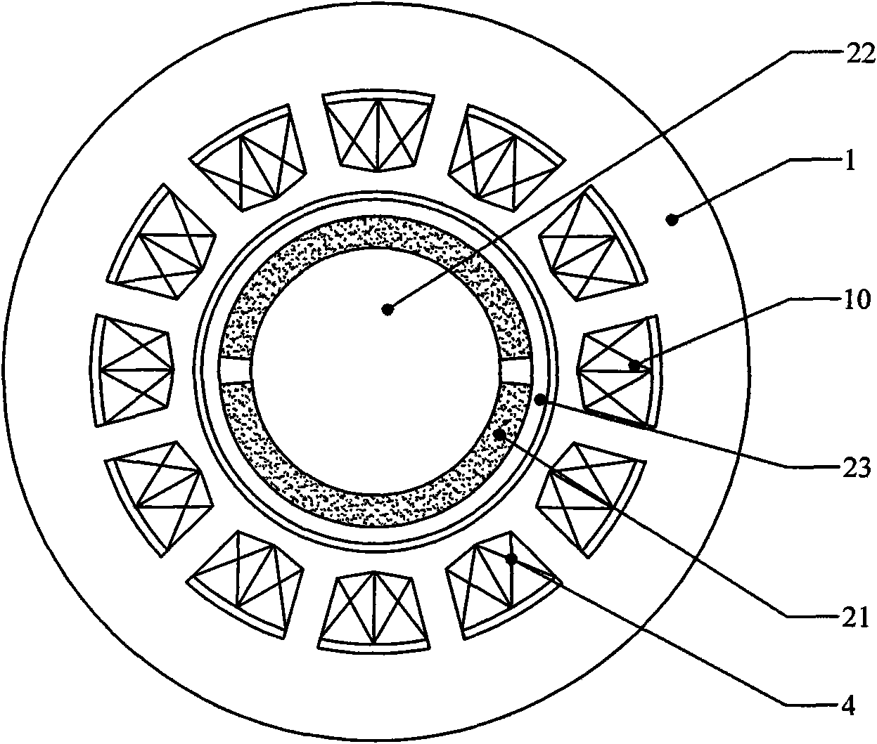
[0011] Specific embodiment one: A kind of high-efficiency high-speed permanent magnet synchronous motor described in this embodiment has an inner rotor structure, which includes a stator, a rotor and an air gap. The rotor is composed of a permanent magnet 21, a permanent magnet sheath 23 and a rotating shaft 22. The stator Including the stator core and winding 4, the stator core 1 is cylindrical, and on the side close to the inner wall of the stator core 1, there are a plurality of cogged through holes 10 along the axial direction, the bottom of the cogged through holes 10 and the stator core 1 The minimum radial thickness of the inner wall is less than 2 mm, and the armature winding 4 is embedded in the alveolar through hole 10 near the axis side, and the armature winding 4 is concentrated short-distance winding or distributed winding.
[0012] When the winding 4 is a concentrated short-distance winding, it can be realized by a stringing process. Each phase winding is formed b...
specific Embodiment approach 2
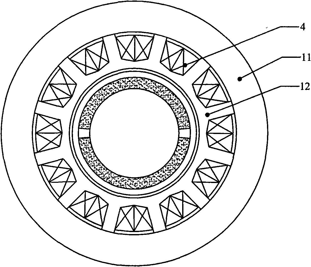
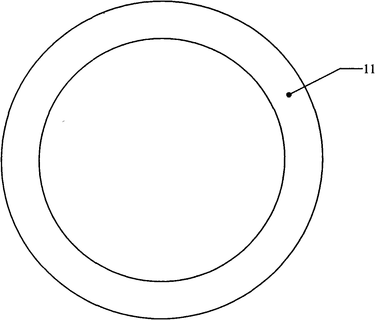
[0016] Embodiment 2: The difference between this embodiment and the high-efficiency high-speed permanent magnet synchronous motor described in Embodiment 1 is that the stator core is a split structure, and the stator core is composed of a yoke core 11 and a tooth core 12. Composition, the yoke core 11 and the tooth core 12 are both cylindrical, and on the outer peripheral surface of the tooth core 12, there are a plurality of holes parallel to the central axis of the tooth core 12 along the axial direction. The tooth slot 121 , the armature winding 4 is embedded in the tooth slot 121 , the permanent magnet 21 in the rotor is fixed on the rotating shaft 22 , and the permanent magnet sheath 23 is fixed outside the permanent magnet 21 .
[0017] In this embodiment, the inner wall of the yoke core 11 and the tooth slot 121 on the tooth core 12 form the slot through hole 10 for embedding the winding. The yoke core 11 and the tooth core 12 can keep rotating synchronously. The end o...
specific Embodiment approach 3
[0020] Embodiment 3: The difference between this embodiment and the high-efficiency high-speed permanent magnet synchronous motor described in Embodiment 1 is that the stator core is a split structure, and the stator core is composed of a yoke core 11 and a tooth core 12. A plurality of straight slots 111 parallel to the central axis of the yoke core 11 are formed on the inner peripheral surface of the yoke core 11 in the axial direction. The number is the same; the shape of the end of the tooth 122 on the outer circumference of the tooth core 12 is the same as the shape of the inner wall of the straight groove 111 on the inner wall of the yoke core 11, and the end of the tooth 122 of the tooth core 12 is the same as that of the yoke The straight grooves 111 on the inner wall of the core 11 are engaged.
[0021] When the high-speed permanent magnet synchronous motor described in this embodiment has 12 slots 121 and the permanent magnet 21 of the rotor is 2 poles, the structure...
PUM
| Property | Measurement | Unit |
|---|---|---|
| Thickness | aaaaa | aaaaa |
Abstract
Description
Claims
Application Information
 - R&D
- Intellectual Property
- Life Sciences
- Materials
- Tech Scout
- Unparalleled Data Quality
- Higher Quality Content
- 60% Fewer Hallucinations
Browse by: Latest US Patents, China's latest patents, Technical Efficacy Thesaurus, Application Domain, Technology Topic, Popular Technical Reports.
© 2025 PatSnap. All rights reserved.Legal|Privacy policy|Modern Slavery Act Transparency Statement|Sitemap|About US| Contact US: help@patsnap.com