Safe brewing pot

A brewing pot and safe technology, which can be used in household containers and other directions, and can solve the problems of hygiene, poor cleanliness, easy to dump, and slippery surfaces.

Inactive Publication Date: 2009-11-11
田蓉蓉
View PDF2 Cites 5 Cited by
  • Summary
  • Abstract
  • Description
  • Claims
  • Application Information

AI Technical Summary

Problems solved by technology

[0004] see Figure 8 In the shown one of the existing liquid brewing devices, the cover 91 of the kettle body 90 in the figure is pivotally connected to the handle 92 on one side of the kettle body 90, whereby the cover 91 is combined with the kettle body 90 and forms a movable Lifting shape, the pot body 90 will cover the cover 91 when brewing. At this time, because the temperature inside the pot body 90 is relatively high, the water vapor of the brewing liquid will rise, so that the inner surface of the cover 91 will produce many Water droplets, when the user opens the cover 91, the cover 91 does not have any flow guiding device, so the water droplets of the cover 91 will follow the kettle body 90, the handle 92 and splash on the plane, causing the plane to be wet. Slippery, poor sanitation and cleanliness
[0005] The existing liquid brewer is equipped with a filter screen for filtering impurities and blocking the brewed material, but the filter screen is directly pressed into the inner wall of the brewer, so the assembly and disassembly of the filter screen is not easy, and the filter screen There is no air hole. When the brewer leaks the brewing liquid, according to the principle of fluid mechanics, the gas in the brewer cannot form convection, and the brewing liquid will not leak smoothly.
[0006] Please refer to my country Patent No. ZL97116221.2 and Taiwan Patent Announcement No. 351971. The diameter of the locking plate located under the cup body is larger than the peripheral edge of the cup bo

Method used


Image

  • Safe brewing pot
  • Safe brewing pot
  • Safe brewing pot

Examples


Embodiment Construction

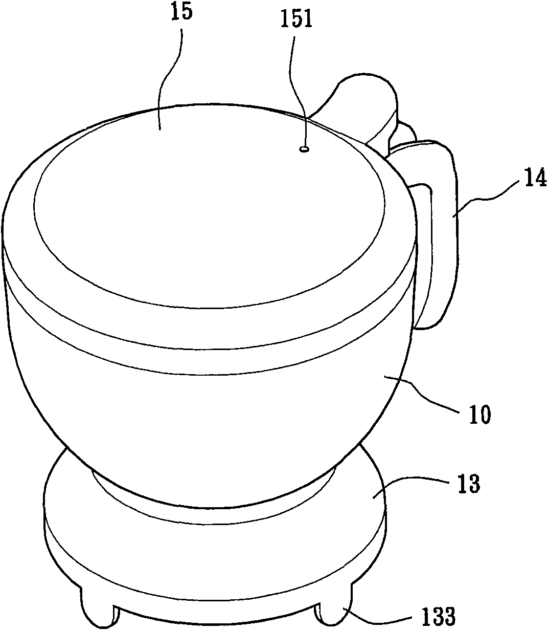
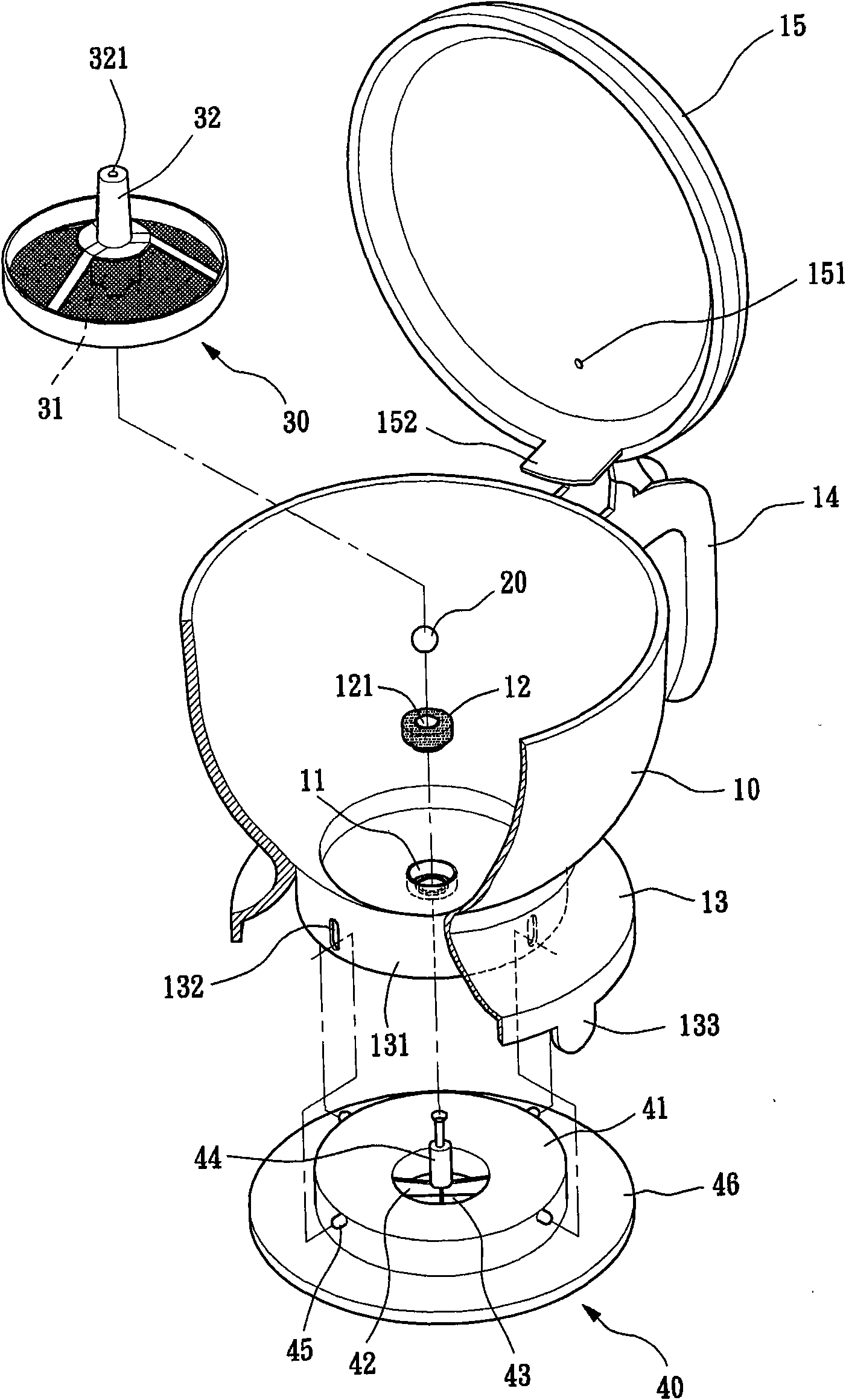
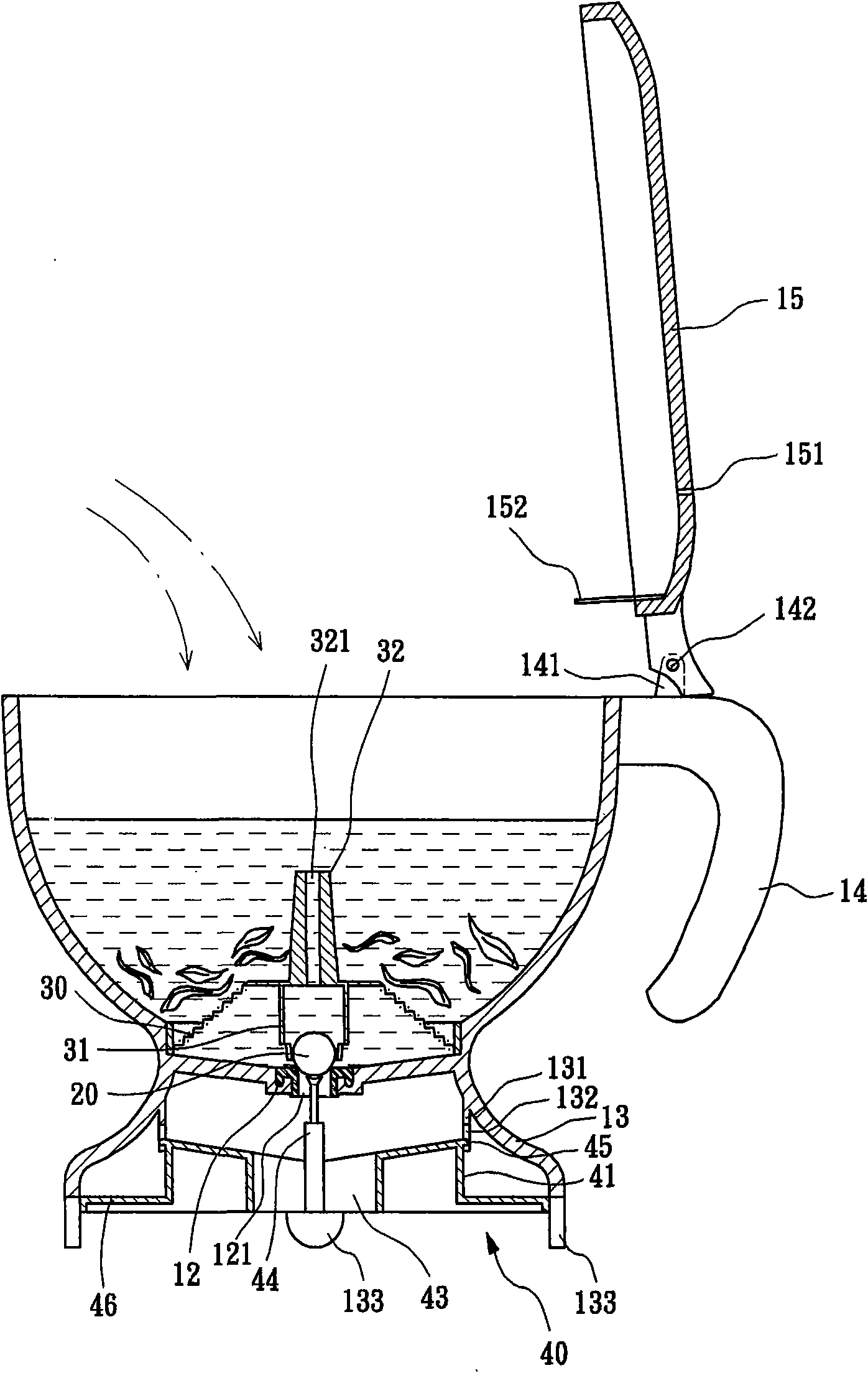
[0047] see figure 1 , figure 2 , image 3 As shown, the present invention includes a pot body 10 , a water stop member 20 , a filter screen 30 , and a locking disc 40 . The following will explain in detail:

[0048] The pot body 10 can be filled with coffee powder, tea leaves, etc. or other brewing materials. There is a through hole 11 on the inner bottom, and the inner bottom has a predetermined slope to effectively guide the brewing liquid to the through hole 11; Bottom 10 bottom peripheral edge is provided with protruding wall 13, and protruding wall 13 inner side is provided with branch 131, and this branch 131 is provided with several chutes 132 that are equidistantly arranged; Handle 14, the handle 14 is provided with a lug 141, the lug 141 is pierced through a shaft 142 to pivotally connect a movable cover 15 that can be lifted, and the cover 15 is provided with a hole that allows gas to pass through 151, and can cover the opening of the kettle body 10.

[0049] ...


PUM


Abstract

The invention relates to a safe brewing pot which comprises a pot body, a water sealing element, a filter screen and a chuck, wherein the bottom of the pot body is provided with a through hole, and the through hole is pivoted with a cover; the water sealing element and the filter screen are arranged at the lower part in the pot body; the chuck is arranged at the lower part of the pot body by a movable structure; the chuck is provided with a protruded column extending to the through hole and a through hole for brewed liquid to flow; the cover is provided with a guide plate; when the cover is lifted, water drops on the cover, which are generated by soaking, are completely guided into the pot body by the guide plate and can not drop on the plane, and the pot has the sanitary and tidy effect; the through hole of the pot body is provided with a sleeve element with a hole; when the water sealing element blocks the hole of the sleeve element, the pot has the leakproof effect; and in addition, the edge under the pot is extended to form a protrusion, the diameter of the protrusion is larger than that of the chuck, the protrusion is provided with a plurality of baseboards which can shield and insulate the chuck, the pot body is difficult to fall when the pot body is placed at the plane, and the pot is more stable and safer.

Description

technical field [0001] The present invention relates to a safe brewing pot, in particular, it refers to the proper design of the cover, the filter screen and the protrusion extending from the periphery of the pot body so that the water droplets on the cover will not splash on the On a flat surface, it is hygienic and tidy, and it has a leak-proof effect when the pot body is not out of water, and it is not easy to tip over when the pot body is placed on a flat surface, which has stability and safety. Background technique [0002] With the prosperity and progress of the city, street coffee chain stores are everywhere recently, and no matter office workers, close friends, relatives and friends, they will use the opportunity of making coffee or tea to shorten the distance between people, because The equipment and time needed to make coffee or tea do not need too much, which is in line with the favorable factors of economy, speed and convenience, so it is widely welcomed by the p...

Claims


Application Information

Patent Timeline
IPC IPC(8): A47G19/14
Inventor 田宝武田林玉梅
Owner 田蓉蓉
Why Eureka
Try Eureka