Braided fabric synchronous dragging device of auxiliary roller mechanism of computer-controlled flat knitting machine

The technology of a traction device and a sub-roller is applied in the field of synchronous traction device for braids, which can solve the problems of damage to the roller 1, blockage, and large movement resistance of the roller 1, and achieve the effect of saving materials and facilitating processing.

Inactive Publication Date: 2009-11-11
JIANGSU JINLONG TECHNOLOGY CO LTD
View PDF4 Cites 9 Cited by
  • Summary
  • Abstract
  • Description
  • Claims
  • Application Information

AI Technical Summary

Problems solved by technology

But the applicant thinks that this patented technical solution still has the following shortcomings: one, it is troublesome to disassemble, because the cloth cover 4 belongs to a wearing part and needs to be replaced. When removing the cloth cover 4, the control panel 6 must be removed Remove it from the roller 1, then pull the transition rod 2 away, and then remove the cloth cover 4; when installing the new cloth cover 4, install it according to the above-mentioned reverse process
However, because the control panel 6 is sleeved on the roller 1 and is also fixed with the transition bar support member 3, it cannot reflect the quick disassembly and assembly of the control panel 6, hindering the quick replacement of the cloth cover 4; two, the roller 1 Because the lower end of the control board 6 is set on the roller 1 through a large through hole, the shavings of the fabric yarn during the production process will enter the matching gap between the control board 6 and the roller 1, causing resistance. stagnation, and even damage the roller 1; third, the processing difficulty of the control board 6 is large and the material consumption is large

Method used


Image

  • Braided fabric synchronous dragging device of auxiliary roller mechanism of computer-controlled flat knitting machine
  • Braided fabric synchronous dragging device of auxiliary roller mechanism of computer-controlled flat knitting machine

Examples


Embodiment Construction

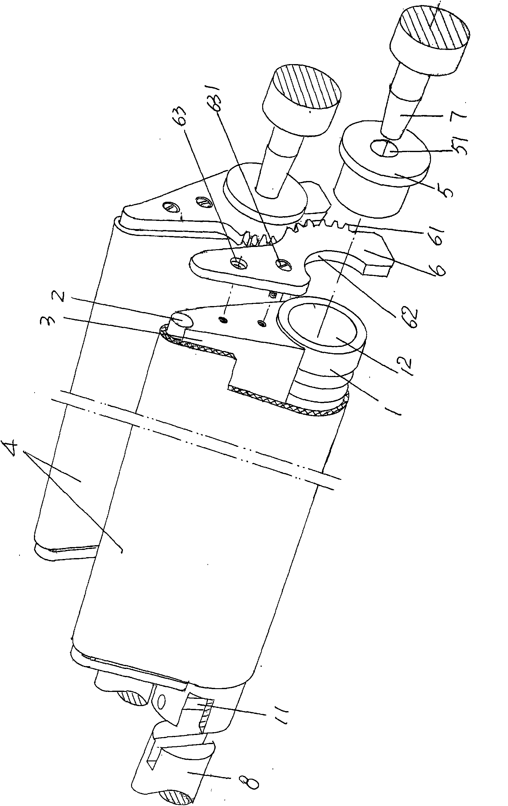
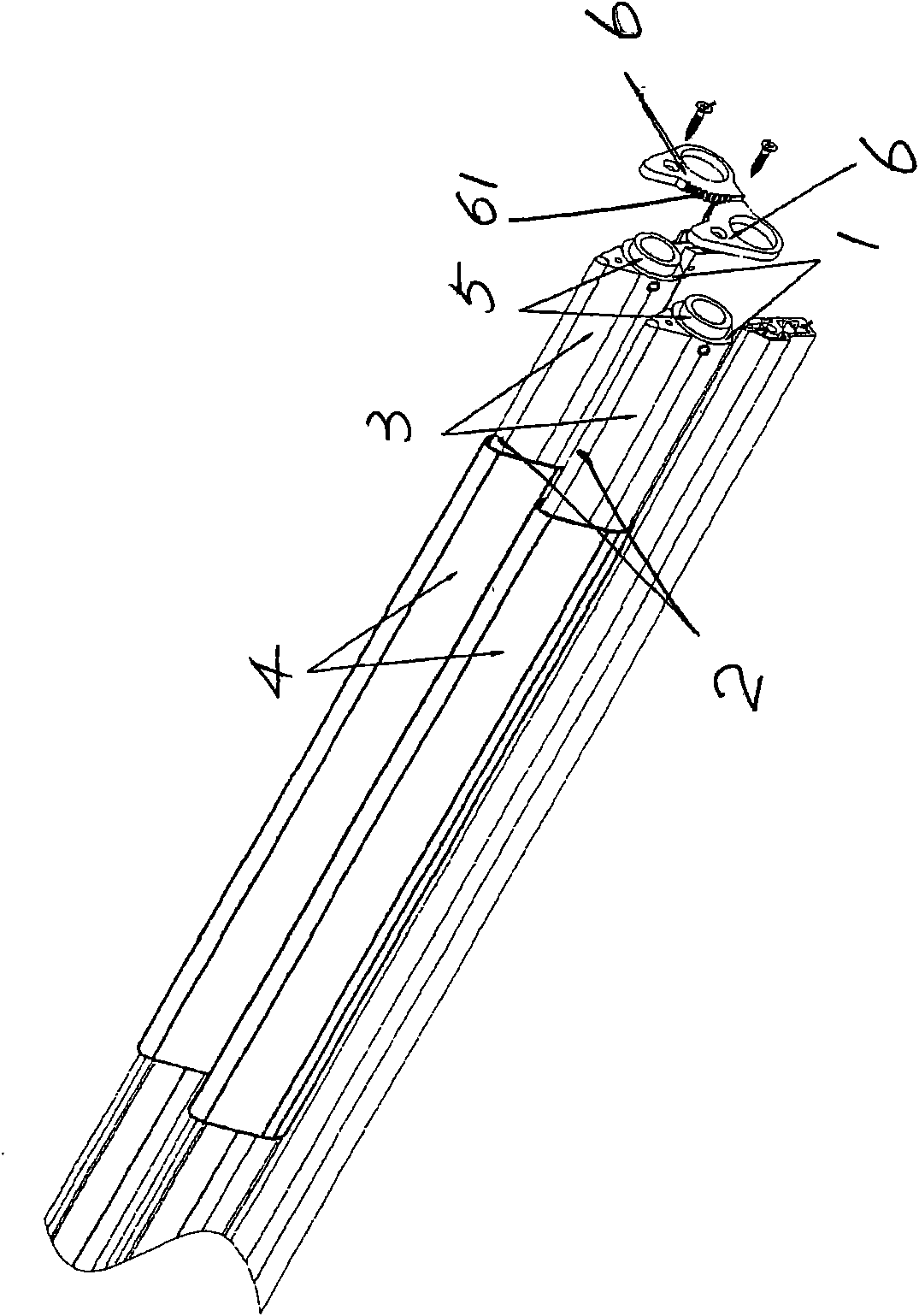
[0012] please see figure 1 , according to professional knowledge, the synchronous traction devices for braided fabrics are configured in pairs, and the number of parts and the installation relationship of the two are exactly the same, so the applicant only chooses one to explain below. Roller 1 has a corrugated structure (bellows), and the left end is connected to the driving shaft 8 of the power transmission device of the auxiliary roller mechanism through the connecting tenon 11. The right end of the roller 1 is inserted into the roller bushing 5 (also called the roller shaft head) and The support 7 of the auxiliary roller mechanism is pivotally connected, specifically: insert one end of the roller bushing 5, that is, the left end shown in the figure, into the through hole 12 of the roller 1, and insert the other end of the roller bushing 5, that is, the hole 51 at the right end shown in the figure. Cooperate with the support 7 , specifically, make the end of the support 7 ...


PUM


Abstract

The invention provides a braided fabric synchronous dragging device of an auxiliary roller mechanism of a computer-controlled flat knitting machine, and belongs to the technical field of knitting machinery. The braided fabric synchronous dragging device comprises rollers which are configured in pairs, a transient rod, a transient rod support piece, a cloth clamping sleeve, a roller bush and a control panel; one end of each roller is connected with a power transmission device, while the other end is pivoted with a pedestal of the auxiliary roller mechanism; the transient rod support piece is arranged on the roller; the transient rod is arranged on the top of the transient rod support piece; the cloth clamping sleeve covers on the roller, the transient rod and the transient rod support piece; the upper end of the control panel is fixed with the transient rod support piece, while the other end is matched with the roller; and the lower end of the control panel is provided with engaging teeth. The braided fabric synchronous dragging device is characterized in that: the lower end of the control panel is provided with a semi-circular groove which is matched with the roller, and the engaging teeth correspond to the back of the semi-circular groove. The braided fabric synchronous dragging device has the advantages of convenient processing, material conservation, convenient assembly and disassembly, and good effects of reducing the kinetic resistance of the roller and protecting the roller.

Description

technical field [0001] The invention belongs to the technical field of knitting machinery, and in particular relates to a knitting synchronous pulling device of an auxiliary roller mechanism of a computerized flat knitting machine. Background technique [0002] The structure and function of the sub-roller mechanism of the computerized flat knitting machine can be passed through the full computer recommended by a kind of sub-roller device of the knitting flat knitting machine introduced by the Chinese Utility Model Patent Authorization Announcement No. CN2905846Y and the Chinese Patent Invention Application Publication No. CN1928182A The auxiliary roller mechanism of the flat knitting machine and the auxiliary roller mechanism of the computerized flat knitting machine disclosed in Chinese invention patent application publication number CN101225576A are understood in detail. [0003] The knitted fabric synchronous traction device is driven by the power transmission device of t...

Claims


Application Information

Patent Timeline
Patent Type & Authority Applications(China)
IPC IPC(8): D04B15/90
Inventor 金永良张和中兰先川赵建生
Owner JIANGSU JINLONG TECHNOLOGY CO LTD
Why Eureka
Try Eureka