Vertical type wind energy machine with rotary vanes with a plurality of cambered surfaces

A wind energy machine and leaf vertical technology, applied in the field of multi-arc rotary blade vertical wind energy machine, can solve the problems of difficult installation and maintenance, large floor space, low conversion efficiency, etc., and achieve high installation height, installation and maintenance Convenience and low conversion efficiency

Inactive Publication Date: 2009-11-11
陈小兵
0 Cites 4 Cited by

AI-Extracted Technical Summary

Problems solved by technology

The wind energy conversion equipment known to the general public is a kind of fan whose axial direction is horizontal and the blades rotate vertically. In order to obtain higher power, the diameter of the rotating blades is large, the position of the axis center is very high, and it occupies a large area. It is difficult to ins...

Method used

Fig. 13 is multi-arc surface rotary vane vertical wind energy machine multi-layer multi-sheet array elevation view: by (30), the first layer of blades, (31), the second layer of blades, (32), the third layer Blade, and (2), shaft beam, (5), power take-off gear, (22), steel structure, (23), diagonal stay rod form a large-scale multi-arc rotar...

Abstract

A vertical wind energy machine with rotary vanes has the characteristics as follows: a gear is driven by a rotor which is arranged vertically and rotates horizontally to rotate for outputting power, wherein the rotor consists of a transmission shaft, a rotating shaft beam and a plurality of annular arrays of rotary vanes with a plurality of cambered surfaces, the windward surface of each rotary vane consists of the plurality of cambered surfaces, thus changing the windward angle of the vane and increasing the air resistance and the effective working scope of the wind surface; the back of the rotary vane is a smooth plane for reducing the resistance, and the revolving shaft of the rotary vane is arranged eccentrically and utilizes the asymmetric force applied at two sides thereof to obtain auto rotation power; when the wind is blowing, the cambered surfaces of the rotary vanes accept the wind force for generating thrust and are prevented and limited by a bumper guard, the rotary vanes use the biggest work area to accept the wind force fully and drive the rotor to rotate; and when rotating to the backs of the rotary vanes and bearing the wind force action, the rotor rotates automatically downwind and takes the side direction as wind surface due to the asymmetric force applied at the two sides of the rotary vanes, thus obtaining the smallest wind area, realizing unilateral force of the rotor and resulting in high-power rotation.

Application Domain

Renewable energy generationMachines/engines +1

Technology Topic

Wind forceRotational axis +3

Image

  • Vertical type wind energy machine with rotary vanes with a plurality of cambered surfaces
  • Vertical type wind energy machine with rotary vanes with a plurality of cambered surfaces
  • Vertical type wind energy machine with rotary vanes with a plurality of cambered surfaces

Examples

  • Experimental program(1)

Example Embodiment

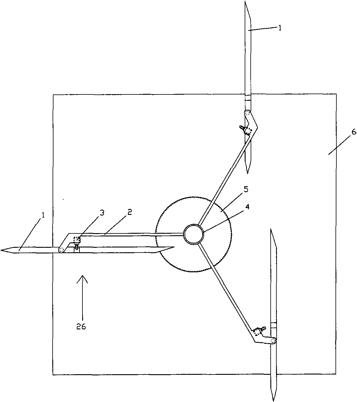
[0020] figure 1 It is a top view of a multi-camber rotary vane vertical wind energy machine: (1), multi-camber rotary blades, (2), shaft beam, (3), buffer protector, (4), drive shaft, (5), Power output gear, (6), base composition.
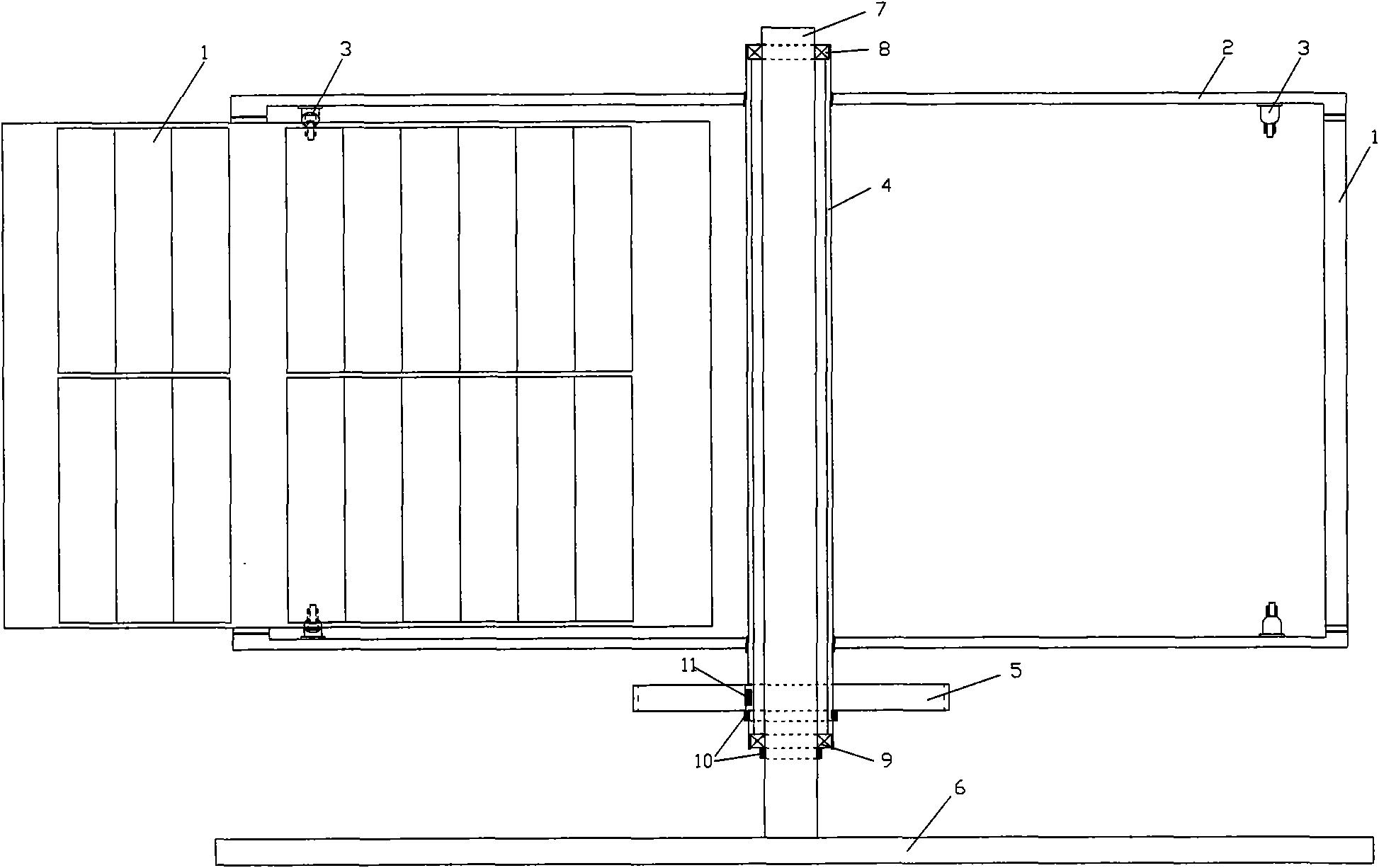
[0021] figure 2 It is the longitudinal section structure diagram of the multi-cambered rotary vane vertical wind energy machine: the figure consists of (1), multi-cambered rotating blades, (2), shaft beam, (3), buffer protector, (4), and drive shaft , Constitute the rotor part, (6), the base, (7), the vertical shaft constitute the frame part, after installation (8), roller bearing, (9), tapered roller bearing, (10), retaining ring, (11) ), key, (5), the power output gear constitutes a multi-curved rotary vane vertical wind energy machine.
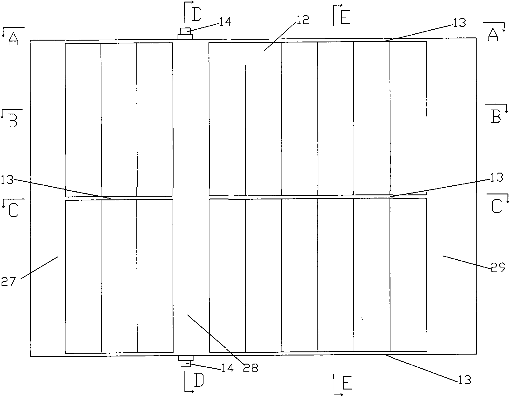
[0022] image 3 It is a plan view of a multi-cambered rotating blade: (12), arc surface, (13), transverse stiffener, (14), blade shaft head, (27), front column, (28), center column, (29) , The rear pillar is composed of lightweight, elastic and aging resistant materials.
[0023] Figure 4 It is the A-A, B-B, C-C, D-D, E-E, F-F cross-sectional structure diagram of the multi-curved rotating blade.
[0024] Figure 5 It is a schematic diagram of the work of the multi-cambered rotating blade: the circular motion of a piece of (1), the multi-cambered rotating blade is illustrated, when (1), the multi-cambered rotating blade and (2), the shaft beam moves from position K to A Reduce the included angle when the position rotates, (1), the multi-curved rotating blade is in contact with (3), the buffer protector and is restricted by (3), the buffer protector, until the G position, where the D position is (1), The maximum wind-receiving area of ​​the multi-cambered rotating blades, at positions B, C, E, F (12), the arc surface changes (1), the wind-receiving angle of the multi-cave rotating blades increases the wind area and resistance When it exceeds the G position (1), the back of the multi-curved rotating blade receives the force of the wind, because (1), the rotating shaft of the multi-curved rotating blade is eccentrically arranged, and the force on both sides of the rotating shaft is different , Make (1), multi-curved rotating blades to rotate, face (26) sideways, obtain the smallest wind-receiving area with wind direction, and keep it from H position to A position, so that there are generated on both sides of the rotor The asymmetric force causes the rotor to rotate.
[0025] Figure 6 It is the longitudinal section structure diagram of the bearing part of the multi-cambered rotating blade: (1), the multi-cambered rotating blade and (14), the blade shaft head are integrated, after installation (8), roller bearing and (9), tapered roller The sub-bearing is connected with (2) and the shaft beam to ensure that the blade can move freely.
[0026] Figure 7 It is a detailed drawing of the vertical shaft, transmission shaft, and power output gear: (7) in the figure, the vertical shaft is the main component supporting the rotor part, and (4), the transmission shaft passes through (9), tapered roller bearings and (8, vertical shaft bearings (9), the tapered roller bearing must bear the weight of the rotor to ensure that the friction force is small when the rotor rotates, and it is positioned by (10), the retaining ring; (4), the drive shaft and (5), the power output The gear is fixed by (11), key and (10), and retaining ring. Power output can also be carried out through couplings, pulleys, and chains. Here, gears are used as an example.
[0027] Figure 8 It is the outline drawing of the buffer protector components: (15) in the figure, the buffer protector roller and (16), the buffer piston and the buffer protector shell, assembled together, fixed to (2), the shaft beam with (18), bolts .
[0028] Picture 9 It is a schematic diagram of the internal workings of the buffer protector: (16) in the figure, the buffer piston and (20), the spring are installed in the buffer protector shell, and grease is added, in use (18), bolts and (19), end cover Closed, when (16), the cushion piston and (15), the cushion protector roller are compressed by (1), the multi-curved rotating blade, the spring is compressed (20), and the impact force of the blade is absorbed to protect the blade.
[0029] Picture 10 It is a schematic diagram of the operation of the multi-curved rotating blade and the buffer protector: (3) in the figure, the buffer protector and (2), the shaft beam (18), bolt installation and fixation; in normal operation (1), the multi-arc rotation The blade rotates with the rotor revolution Figure 5 In the middle A position, the rotation of (2), the shaft beam reduces the angle and (3), the buffer protector contact, (20), the spring absorbs the impact force and restricts (1), the movement of the multi-curved rotating blade , Make (1), multi-curved rotating blades receive wind with the multi-curved working surface, and complete the buffering working process; when (1), multi-curved rotating blades are subjected to super strong wind, the unilateral force exceeds ( 3) The buffering capacity of the buffer protector, compression (20), spring (21), blade cushioning (3), the limit of the buffer protector is to receive wind from the side to protect the blade, completing the protection work process.
[0030] Picture 11 It is the detailed drawing of the retaining ring components: (10), the retaining ring is for (5), the power output gear and (11), the tapered roller bearing to limit and fix and bear the weight above, (10), the retaining ring is in two halves The ring components are connected by (24) and bolts, and an annular groove is machined on the shaft of the installation position to install (10) and the inner ring of the retaining ring.
[0031] Picture 12 It is a top view of a multi-layer and multi-piece array of multi-camber rotary blade vertical wind energy machine: (30), the first layer of blades, (31), the second layer of blades, (32), the third layer of blades, and (22), Large-scale multi-arc rotary vane vertical wind energy machine composed of steel structure.
[0032] Figure 13It is an elevation view of a multi-layer multi-slice array of a multi-curved rotary vane vertical wind energy machine: (30), the first layer of blades, (31), the second layer of blades, (32), the third layer of blades, and ), the shaft beam, (5), the power output gear, (22), the steel structure, (23), and the oblique tie rods form a large multi-curved rotary vane vertical wind energy machine, through multiple blades with different wind angles The layer makes (4), the torque transmitted by the drive shaft stable and continuous, and drives (24), the speed increaser, (25), and the generator to work. The steel structure enhances the overall stability outside the rotor rotation area.

PUM

no PUM

Description & Claims & Application Information

We can also present the details of the Description, Claims and Application information to help users get a comprehensive understanding of the technical details of the patent, such as background art, summary of invention, brief description of drawings, description of embodiments, and other original content. On the other hand, users can also determine the specific scope of protection of the technology through the list of claims; as well as understand the changes in the life cycle of the technology with the presentation of the patent timeline. Login to view more.

Similar technology patents

Biometric identification apparatus

InactiveUS20080037001A1perform accurately and rapidlysimple structure
Owner:HITACHI MEDIA ELECTORONICS CO LTD

Fuel cell

ActiveUS20070207372A1simple structuremaintain durability
Owner:HONDA MOTOR CO LTD

Isolation implant in abdominal aorta external and internal iliac artery cavity

Owner:SECOND MILITARY MEDICAL UNIV OF THE PEOPLES LIBERATION ARMY

Classification and recommendation of technical efficacy words

  • Simple structure
  • Easy installation and maintenance

Sharing system for air-conditioning coat

InactiveCN107440179ASimple structureeasy to wear
Owner:QINGDAO HAIER AIR CONDITIONER GENERAL CORP LTD

Emergency parachuting device and method for multiple-rotor unmanned aerial vehicle

InactiveCN103895870Aavoid aircraft crashSimple structure
Owner:SOUTH CHINA AGRI UNIV +1

Quick pipe connector

Owner:YANG RICHARD

Automatic washing and dewatering combined device of rotary type mop

InactiveCN102370447Areduce volumeSimple structure
Owner:上海祥美网络科技有限公司 +1
Why Eureka
Try Eureka