Method for manufacturing surface crack defect test block for nondestructive flaw detection

A technology for surface crack and non-destructive flaw detection, which is applied in the preparation of test samples, optical testing of flaws/defects, and analysis of solids using sound waves/ultrasonic waves/infrasonic waves, etc. , to achieve the effect of enhancing perceptual and rational cognition

Inactive Publication Date: 2009-11-11
XI AN JIAOTONG UNIV
View PDF0 Cites 43 Cited by
  • Summary
  • Abstract
  • Description
  • Claims
  • Application Information

AI Technical Summary

Problems solved by technology

However, the difference between the artificial defects and the actual defects in the standard test block, as well as the limitations of the

Method used


Image

  • Method for manufacturing surface crack defect test block for nondestructive flaw detection
  • Method for manufacturing surface crack defect test block for nondestructive flaw detection
  • Method for manufacturing surface crack defect test block for nondestructive flaw detection

Examples


Embodiment 1

[0028] (1) Welding test block preparation and filling layer welding

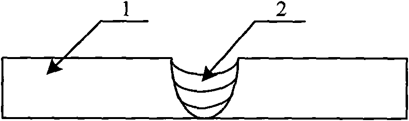
[0029] according to figure 1 As shown in Fig. 1, a bevel is first made on the defect test block 1, and then the welding rod matching the material of the defect test block 1 is used to fill and weld the bevel, and the design crack area is determined on the weld.

[0030] (2) Sprinkle FeS powder on the designed crack area

[0031] Use commercial ferrous sulfide powder 7 (Ferrous sulfide, FeS for short, S ≈ 27%, melting point 1195 ° C), with a particle size range of 20-40 mesh, and spread it on the surface of the weld in the designed crack area.

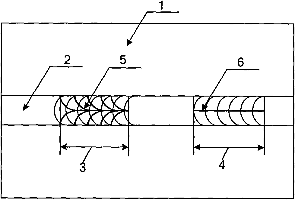
[0032] Formation of herringbone cracks 5 (such as image 3 or Figure 4 ) The mass ratio of ferrous sulfide powder 7 to the deposited metal on the cover is about 1:10, and the spreading width is the same as the groove width (such as figure 2 A design crack area in 3).

[0033] Formation of the central crack 6 (eg image 3 or Figure 4 ) ferrous sulfide powder ...

Embodiment 2

[0044] (1) Welding test block preparation and filling layer welding

[0045] according to figure 1 As shown in Fig. 1, a bevel is first made on the defect test block 1, and then the welding rod matching the material of the defect test block 1 is used to fill and weld the bevel, and the design crack area is determined on the weld.

[0046] (2) Sprinkle FeS powder on the designed crack area

[0047] Use commercial ferrous sulfide powder 7 (Ferrous sulfide, FeS for short, S ≈ 27%, melting point 1195 ° C), with a particle size range of 20-40 mesh, and spread it on the surface of the weld in the designed crack area.

[0048] Formation of herringbone cracks 5 (such as image 3 or Figure 4 ) The mass ratio of ferrous sulfide powder 7 spreading amount to the deposited metal on the cover surface is about 1:8, and the spreading width is the same as the groove width (such as figure 2 A design crack area in 3).

[0049] Formation of the central crack 6 (eg image 3 or Figure 4 )...

Embodiment 3

[0060] (1) Welding test block preparation and filling layer welding

[0061] according to figure 1 As shown in Fig. 1, a bevel is first made on the defect test block 1, and then the welding rod matching the material of the defect test block 1 is used to fill and weld the bevel, and the design crack area is determined on the weld.

[0062] (2) Sprinkle FeS powder on the designed crack area

[0063] Use commercial ferrous sulfide powder 7 (Ferrous sulfide, FeS for short, S ≈ 27%, melting point 1195 ° C), with a particle size range of 20-40 mesh, and spread it on the surface of the weld in the designed crack area.

[0064] Formation of herringbone cracks 5 (such as image 3 or Figure 4 ) The mass ratio of the ferrous sulfide powder 7 spread to the capping welded metal is about 1:12, and the spread width is the same as the groove width (such as figure 2 A design crack area in 3).

[0065] Formation of the central crack 6 (eg image 3 or Figure 4 ) ferrous sulfide powder ...


PUM

PropertyMeasurementUnit
Granularityaaaaaaaaaa
Melting pointaaaaaaaaaa

Abstract

The invention discloses a method for manufacturing a surface crack defect test block for nondestructive flaw detection. By using the mechanism of production of surface cracks in the process of welding, the invention provides a method for quickly manufacturing the surface crack defect test block. The method manufactures a commonly used surface weld crack test block through the approaches of adding sulfur elements into a welding seam, reasonably controlling a welding process and the like. The surface cracks manufactured by the method are different from artificial defects of a commonly used flaw detection standard test block, the crack defects are real and practicable, can be applied to nondestructive flaw detection methods of ultrasonic flaw detection, penetrant flaw detection and the like, and are significant for training and evaluation of license changing and obtaining of nondestructive flaw detection personnel, and improving perceptual and rational knowledge of surface crack defect flaw detection signals of the nondestructive flaw detection personnel.

Description

technical field [0001] The invention belongs to the field of non-destructive flaw detection, and relates to a method for making a defect test block, in particular to a method for making a surface crack defect test block for non-destructive flaw detection. Background technique [0002] Non-destructive testing is an emerging comprehensive applied technical discipline, which is a discipline that measures and evaluates various internal or external defects of materials without destroying or damaging the object being inspected. Non-destructive testing technology is an important means to achieve quality control, improve technology, reduce costs, and ensure safe operation of equipment. It has become an indispensable and important part of the manufacturing and use of modern industrial products. In recent years, with the development of applied physics, electronic technology, material science, etc., non-destructive testing methods and testing accuracy have been greatly enriched and dev...

Claims


Application Information

Patent Timeline
IPC IPC(8): G01N1/28G01N29/04G01N21/91
Inventor 牛靖张建勋巨西民朱彤张林杰付强
Owner XI AN JIAOTONG UNIV
Why Eureka
Try Eureka