Flaky medium conveying mechanism
A technology of sheet-like medium and transmission mechanism, which is applied in thin material processing, transportation and packaging, object supply, etc., can solve the problems of high cost, large volume of transmission mechanism, and difficult maintenance of transmission mechanism, and achieves small occupied space and reduced cost. , the effect of reducing the size of the device
- Summary
- Abstract
- Description
- Claims
- Application Information
AI Technical Summary
Problems solved by technology
Method used
Image

Examples
Embodiment Construction
[0017] The present invention will be further described below in conjunction with preferred embodiments and accompanying drawings, but the embodiments of the present invention are not limited thereto.
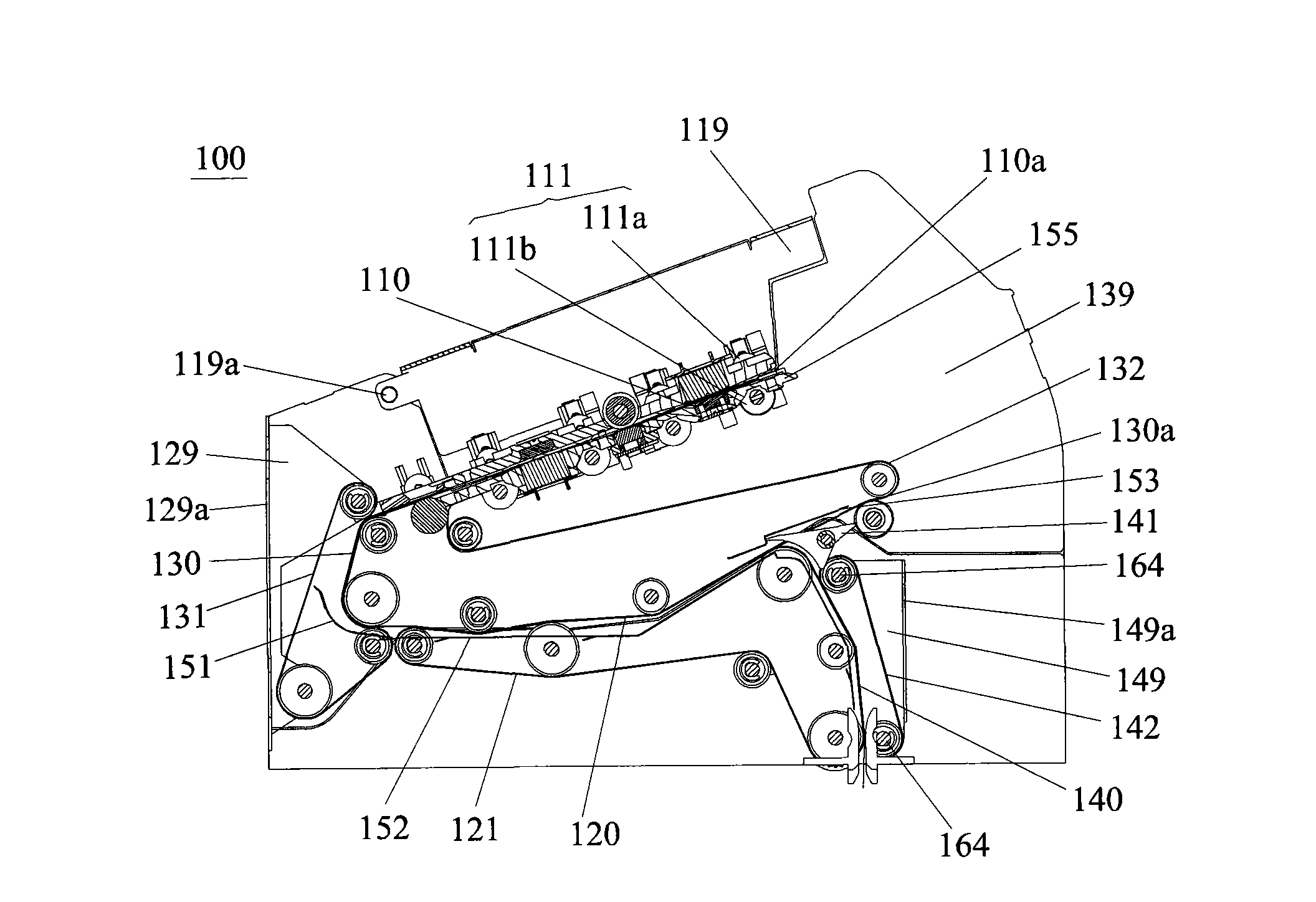
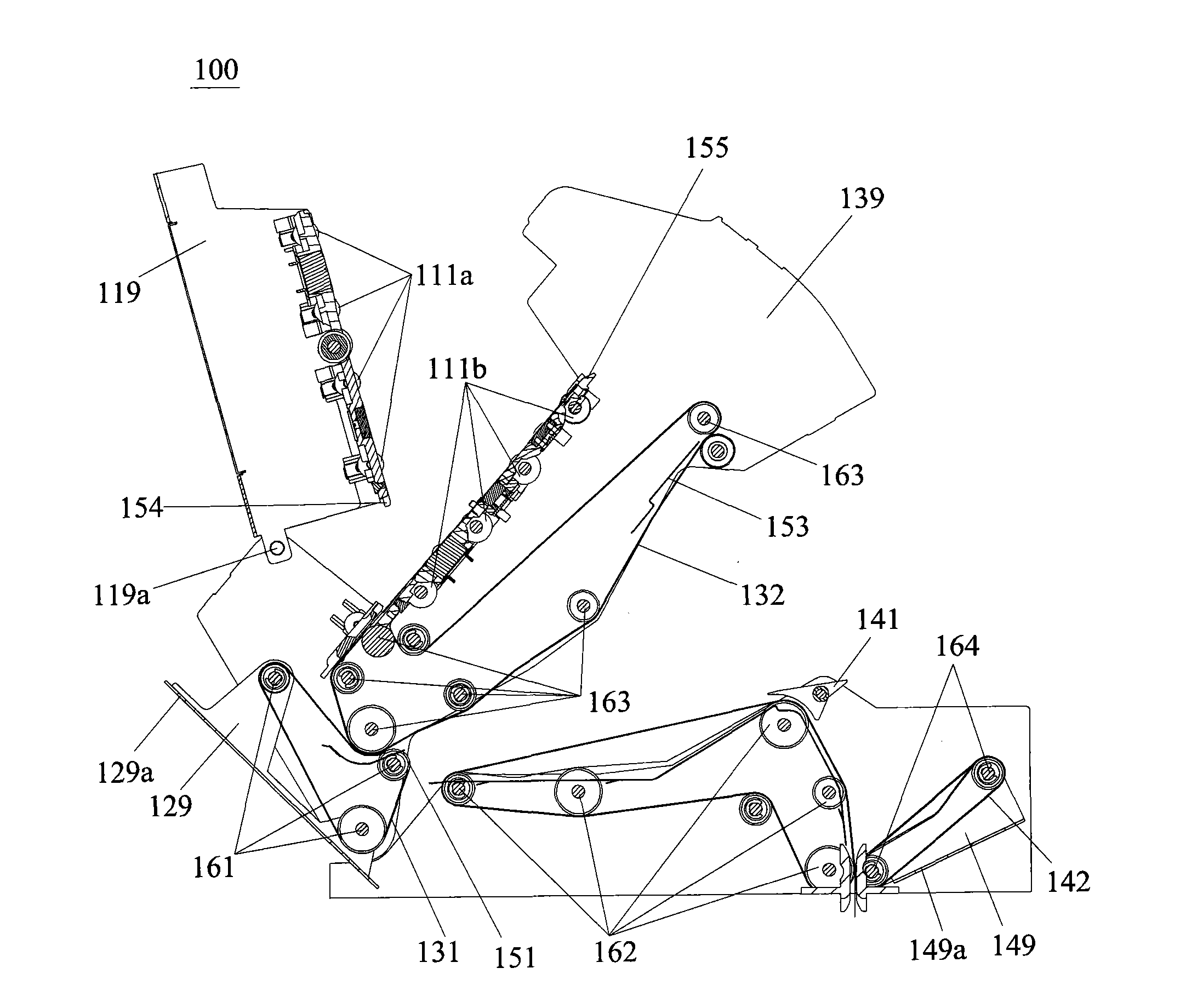
[0018] refer to figure 1 , the sheet medium transmission mechanism 100 of this embodiment is a deposit channel in a bank teller machine. Such as figure 1 As shown, the sheet medium transmission mechanism 100 of this embodiment includes a first transmission channel 110 , a second transmission channel 120 and a first transition channel 130 . One end of the first transmission channel 110 is a medium input port 110 a, the other end is connected to the first transition channel 130 , and one end of the second transmission channel 120 is connected to the first transition channel 130 . The first transmission channel 110 and the second transmission channel 120 are stacked, and the first transmission channel 110 is located above the second transmission channel 120 . In the case of the ...
PUM
 Abstract
Description
Claims
Application Information
PatSnap Eureka turns technology decisions into work you can execute. Powered by our Innovation Knowledge Graph, it runs expert workflows across engineering, life sciences, materials and intellectual property. Get your review-ready output in minutes.


