Turbine blade compound cooling structure with sunken internal pin

A turbine blade and composite cooling technology, applied in the directions of blade support elements, heat exchange equipment, engine elements, etc., can solve problems such as flow resistance, reduction in overall efficiency of gas turbines, and reduction in blade cooling efficiency

Inactive Publication Date: 2009-11-18
SHANGHAI JIAO TONG UNIV
View PDF0 Cites 10 Cited by
  • Summary
  • Abstract
  • Description
  • Claims
  • Application Information

AI Technical Summary

Problems solved by technology

However, due to the increased wall thickness, the cooling efficiency of the blades is reduced and the overall efficiency of the gas turbine is thus reduced
[0004] On the other hand, the pin-fin array structure is usually used inside the tra

Method used


Image

  • Turbine blade compound cooling structure with sunken internal pin
  • Turbine blade compound cooling structure with sunken internal pin
  • Turbine blade compound cooling structure with sunken internal pin

Examples


Embodiment Construction

[0021] The embodiments of the present invention are described in detail below in conjunction with the accompanying drawings: this embodiment is implemented on the premise of the technical solution of the present invention, and detailed implementation methods and specific operating procedures are provided, but the protection scope of the present invention is not limited to the following the described embodiment.

[0022] This embodiment illustrates the present invention by taking the pin-fin recessed compound cooling structure inside the trailing edge of the turbine blade as an example.

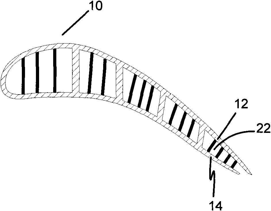
[0023] like figure 1 As shown, this embodiment includes: a turbine blade 10 , a blade flow channel 22 , a pressure side wall surface 14 , and a suction side wall surface 12 . The upper wall surface of the blade flow channel 22 is the suction side wall surface 12 , and the lower wall surface of the blade flow channel 22 is the pressure side wall surface 14 .

[0024] like image 3 and Figu...


PUM


Abstract

The invention relates to a turbine blade compound cooling structure with sunken internal pins, comprising a blade passage and a pin; the cooling structure is characterized by further comprising a sunken part, pins are arranged in the blade passage, the blade passage has at least one internal wall surface provided with sunken parts; the sunken parts are arranged in the blade passage in a dislocation way; the sunken parts are of semisphere or part of the semisphere or cone with top part cut off. In the invention, the pins are respectively connected with two wall surfaces in the blade passage, thus on one hand increasing heat exchange area of cooling fluid and on the other hand consolidating the passage; the sunken parts cause the flowing through to generate vortex, thus improving convection and heat exchange effect between the air stream and wall surface of the blade passage and pin surface; meanwhile, when the air stream flows through the sunken parts, direct impact on the pins by the lower reaches of the fluid body is reduced, thus avoiding increase of flow losses while increasing heat exchange area.

Description

technical field [0001] The invention relates to an internal cooling device for a turbine blade of a gas turbine, in particular to a composite cooling structure with pin-fin recesses inside the turbine blade. Background technique [0002] It is a major trend in the development of modern gas turbines to increase the gas temperature before the turbine, thereby improving the total efficiency of gas turbine energy conversion. The temperature of the gas before the turbine of a modern gas turbine has exceeded the melting temperature of the materials used. Therefore, with the further increase of the gas temperature at the turbine inlet, more efficient and advanced cooling technologies are urgently needed to ensure the temperature level in high-temperature components such as the turbine blades of the gas turbine, and Control the temperature gradient within a reasonable range to ensure normal operation and a sufficient life cycle. In addition, the enhanced cooling technology means th...

Claims


Application Information

Patent Timeline
IPC IPC(8): F01D5/18
CPCF28F3/022
Inventor 饶宇臧述升
Owner SHANGHAI JIAO TONG UNIV
Why Eureka
Try Eureka