C-type arm image correction method based on perspective imaging model calibration

A perspective imaging model and C-arm technology, applied in image enhancement, image analysis, image data processing, etc., can solve problems affecting navigation accuracy and inaccurate C-arm system parameters

Inactive Publication Date: 2009-11-18
BEIHANG UNIV
View PDF0 Cites 46 Cited by
  • Summary
  • Abstract
  • Description
  • Claims
  • Application Information

AI Technical Summary

Problems solved by technology

The advantage is that the calculation is simple, and the disadvantage is that the center of the calibration template, the center of the image intensifier and the radiation source are not on the same line due to the influence of the weight of the

Method used


Image

  • C-type arm image correction method based on perspective imaging model calibration
  • C-type arm image correction method based on perspective imaging model calibration
  • C-type arm image correction method based on perspective imaging model calibration

Examples


Embodiment Construction

[0092] A C-arm image correction method based on perspective imaging model calibration of the present invention will be described in detail below through specific embodiments in conjunction with the selected specific hardware carrier:

[0093] The first case: when the rotation angle of the C-arm is 0 degrees and the distance from the radiation source to the detector is 124cm.

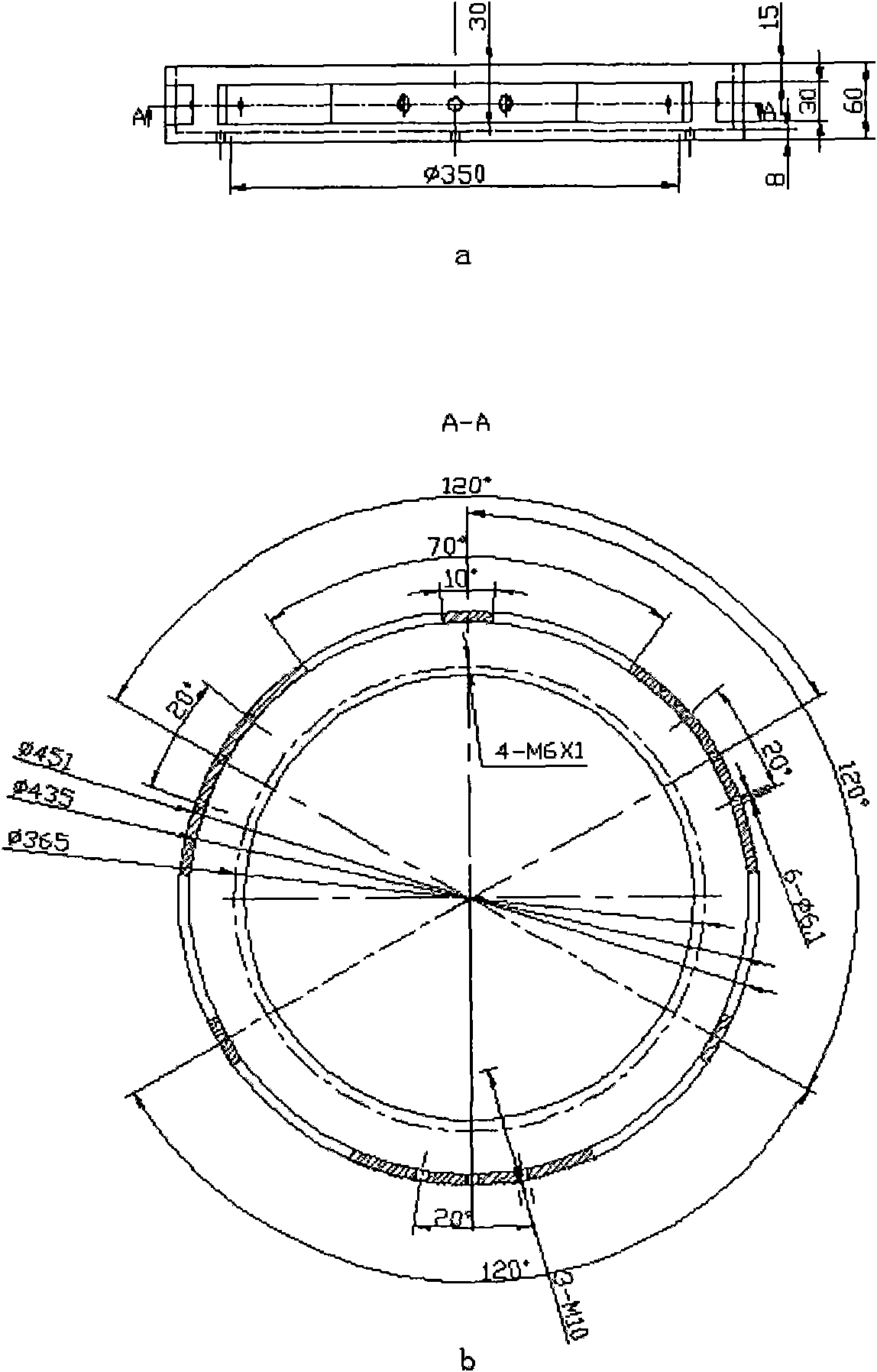
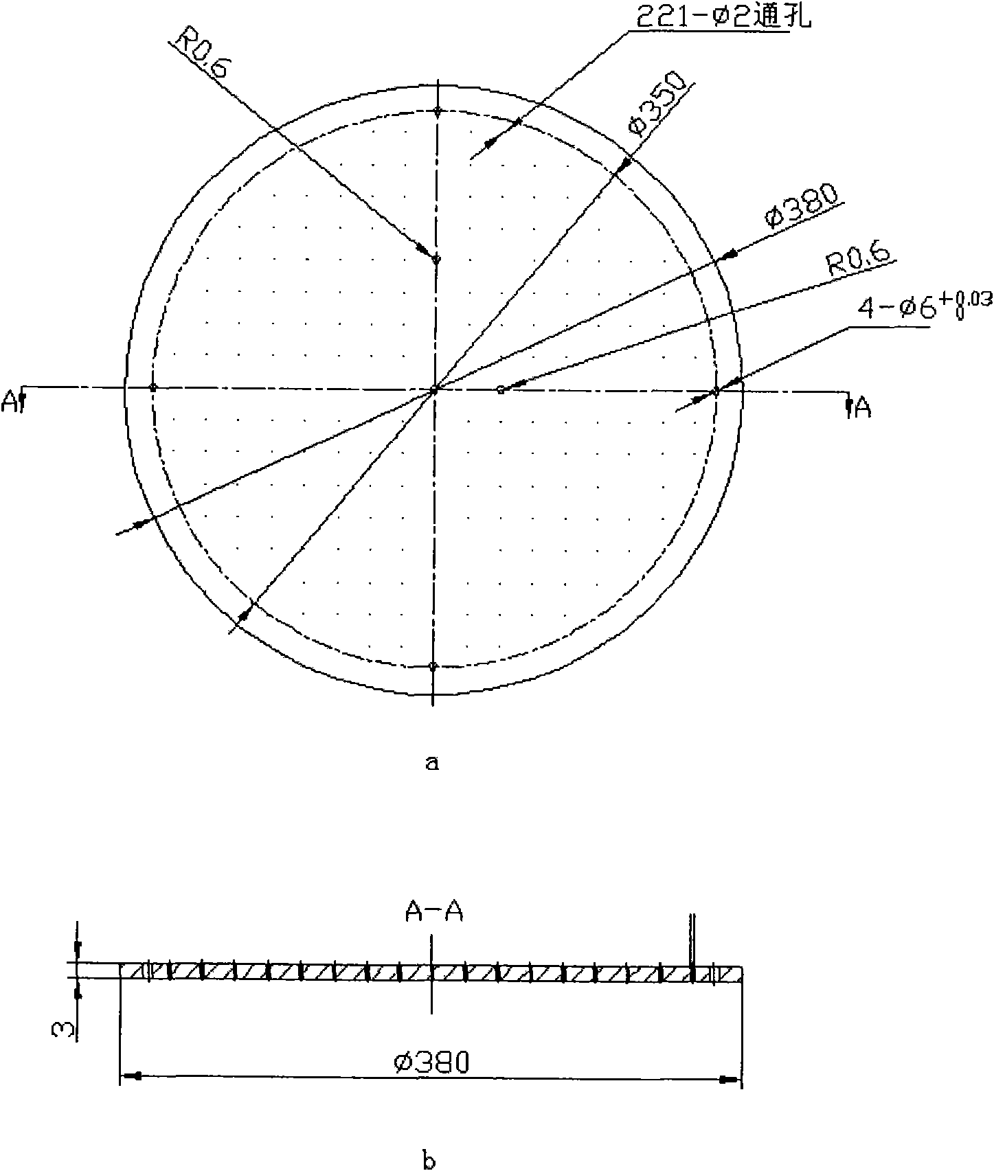
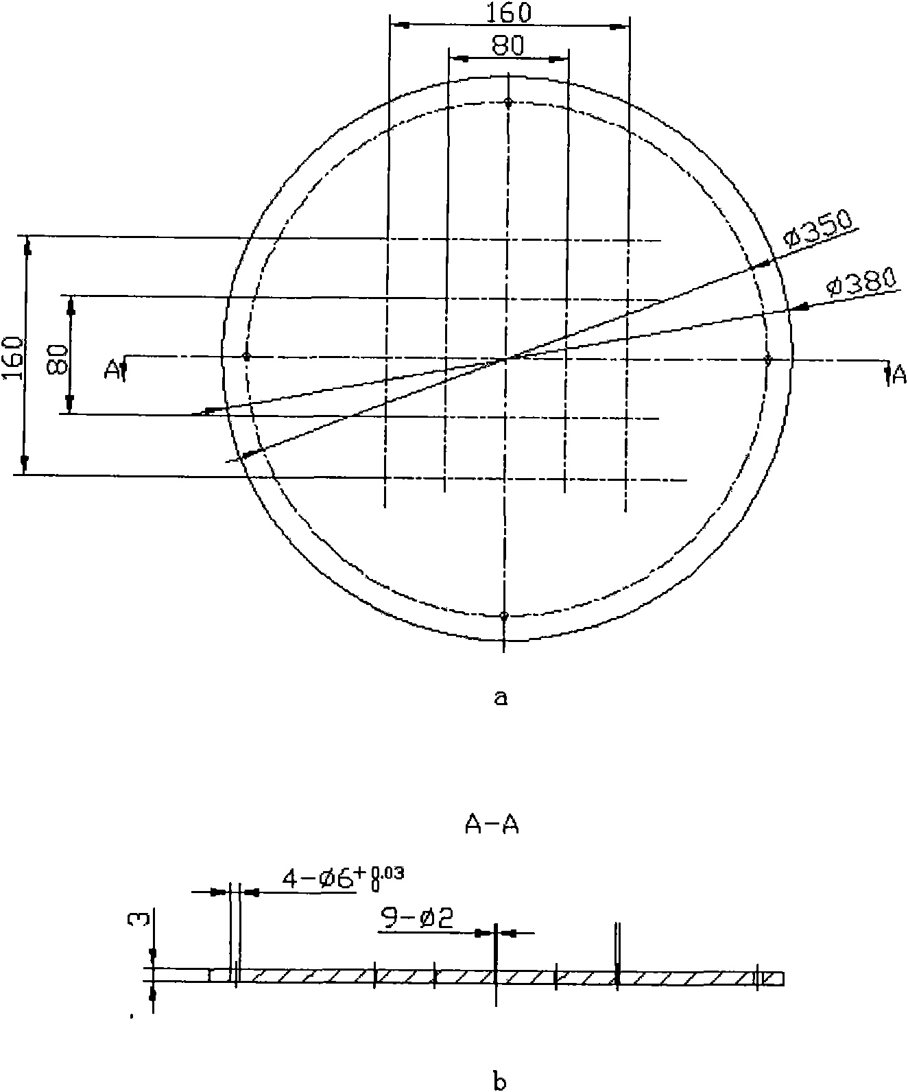
[0094] (1) Design the calibration template for the calibration of the C-arm system. Choose a material that cannot penetrate X-rays to make a double-layer stereoscopic calibration template. In this embodiment, aluminum with a relatively light density is used to reduce the influence of the calibration template's own weight on the system. Such as Figure 9 , the calibration template has two upper and lower layers, and the upper calibration target is distributed with 9 small holes with a diameter of 2mm, and the distribution law is as follows image 3 shown. There are 221 small holes distributed in the c...


PUM

PropertyMeasurementUnit
Diameteraaaaaaaaaa

Abstract

A C-type arm image correction method based on perspective imaging model calibration comprises the following four steps: step 1, designing a calibration panel calibrated by a C-type arm system; step 2, obtaining distortion coordinates of marked points by image processing on distorted images; step 3, calibrating the C-type arm system, including system calibration of three dimensional coordinates of marked points on the calibration panel, perspective imaging models, distortion models and distortion coordinates to obtain perspective imaging parameters; step 4, correcting images, namely, the calibrated perspective imaging models are used for correcting the distorted images. In the method, the C-type arm system calibration and the C-type arm X-ray distorted projected image correction are considered as a whole on line, and the C-type arm system is calibrated and the C-type arm X-ray distorted projected image is corrected based on the perspective imaging model of the camera, thereby changing the traditional method that image correction is first carried out off line and then linear calibration is carried out and ensuring concise and convenient system steps an easy on-line use.

Description

(1) Technical field [0001] The invention relates to a C-arm image correction method based on perspective imaging model calibration, which mainly takes the C-arm system imaging parameter calibration and C-arm X-ray projection distortion image correction as a whole, and calibrates the C-arm based on the perspective imaging model. The C-arm system obtains the internal and external parameters of the C-arm system, and then utilizes the distortion parameters obtained by calibrating the C-arm system to realize an image correction method for distorted C-arm X-ray projection images, which belongs to the field of image processing. (2) Background technology [0002] Image correction is a common image processing method, such as image mosaic after remote sensing image correction, aerial image correction before use, camera image correction for positioning or three-dimensional reconstruction. [0003] At present, there are three types of distortions in C-arm X-ray projection images: pincus...

Claims


Application Information

Patent Timeline
IPC IPC(8): G06T5/00G06T7/00A61B6/03
Inventor 孟偲周付根吕绍杰刘博周晓君
Owner BEIHANG UNIV
Why Eureka
Try Eureka