
Pulse type large beam spot electronic beam generating device

A generation device and electron beam technology, applied in the direction of circuits, discharge tubes, electrical components, etc., can solve problems such as limited energy input control capability, excessively large heat-affected zone of materials, and small electron beam spot area to avoid scattering interference , Avoid radiation pollution and protect the safety of operators

Inactive Publication Date: 2009-11-18
DALIAN UNIV OF TECH
View PDF0 Cites 18 Cited by
  • Summary
  • Abstract
  • Description
  • Claims
  • Application Information

AI Technical Summary

Problems solved by technology

A small number of electron beam devices used for the exploration of electron beam material surface modification technology are only simple modification or combination of the original technology for special treatment occasions, and there are still small electron beam spot areas (about 1mm 2 ), the electron beam current is weak (hundreds of mA), the control ability of energy input is limited, and the heat-affected zone of the material is too large, etc.

Method used


Image

  • Pulse type large beam spot electronic beam generating device

Examples


Embodiment Construction

[0024] Specific embodiments of the present invention will be described below in conjunction with the accompanying drawings and specific implementation methods.

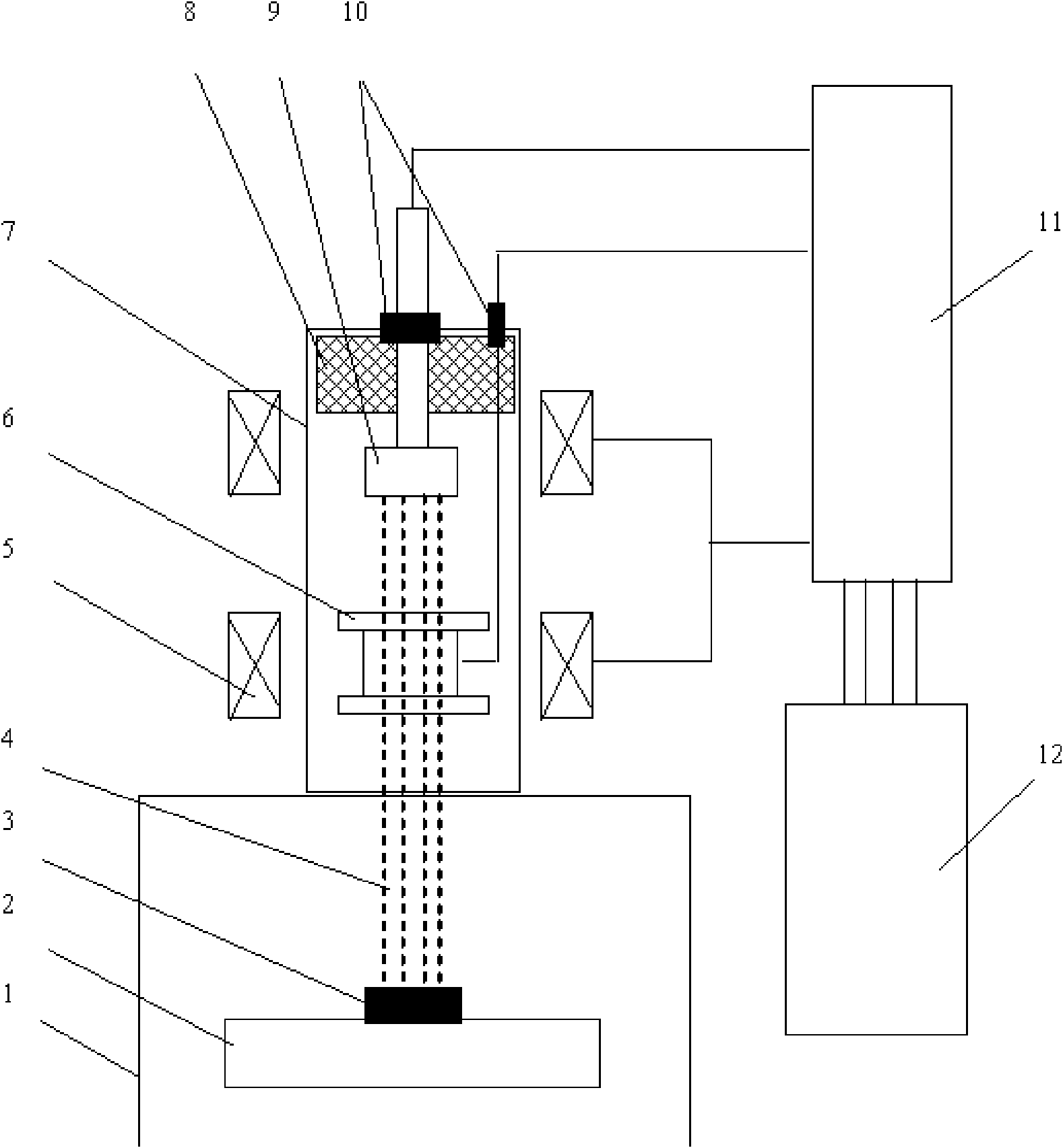
[0025] As shown in FIG. 1 , a pulse-type large-spot electron beam generating device manufactured according to the present invention includes a high-voltage pulse power supply 11 , a timing control circuit 12 , an electron gun 7 and a vacuum chamber 1 .

[0026] The high-voltage pulse power supply 11 provides independent high-voltage outputs for the electron gun cathode 9, the plasma anode 6 and the magnetic field coil 5, respectively 3kV, 15kV and 35kV, wherein the 35kV output is the main pulse applied on the electron gun cathode 9, and the polarity is negative , the high-voltage output can be adjusted between 20 and 35kV according to the specific processing technology requirements.

[0027] The timing control circuit 12 operates the turn-on action of the high-voltage pulse power supply 11 to adjust the timing coordin...


PUM

PropertyMeasurementUnit
Diameteraaaaaaaaaa

Abstract

The invention discloses a pulse type large beam spot electron beam generating device, belonging to the technical field of modification of material surfaces. The device consists of a high-voltage pulse power supply, a time sequence control circuit, an electronic gun and a vacuum chamber. The vacuum chamber is controlled by discharging time sequence of the high-voltage pulse power supply after reaching working pressure; a magnetic field formed in the electronic gun confines the discharge of a plasma anode; a plasma channel is formed between the cathode and the anode of the electronic gun; and the cathode is applied with high-voltage negative pulse so as to form electronic emission on the cathode surface and obtain the pulse electron beam with large beam spots. The device can generate electron beam with accelerating voltage of 20 to 35kV, the pulse duration of 2 to 4Mus, the beam spot area with the diameter of 60mm and repetition frequency of 0.1Hz, and the average energy density of the beam spot is 1 to 6J / cm. The pulse type large beam spot electron beam generating device also has the advantages of reasonable design, simple structure, high degree of automation and the like and is applicable to research and application of modification technique of the material surface.

Description

technical field [0001] The invention belongs to the technical field of material surface modification, and relates to a pulse type large beam spot electron beam generating device. Background technique [0002] Material science is one of the important pillars of the development of human society. With the advancement of modern science and technology, higher requirements are placed on the performance of materials, and material science is facing new challenges. Fatigue, wear and corrosion are the three main failure modes of engineering materials, and they are all closely related to the surface state of materials, such as corrosion of chemical containers and pipelines, wear resistance of tools and molds, fatigue crack initiation on the surface of mechanical parts, etc. The key to improving the performance of these materials is to improve their surface properties. [0003] Material surface modification technology is an important branch of material science research. It uses physic...

Claims


Application Information

Patent Timeline
IPC IPC(8): H01J37/317
Inventor 郝胜智董闯
Owner DALIAN UNIV OF TECH
Learn More