Rectifier circuit

A rectifier circuit and circuit technology, applied to electrical components, AC power input conversion to DC power output, output power conversion devices, etc., can solve problems such as inability to ensure stable output voltage, large harmonic current, and many harmonic components , to achieve the effect of improving efficiency, increasing switching frequency, and realizing simple process

Active Publication Date: 2009-11-18
SHENZHEN SINEXCEL ELECTRIC
View PDF0 Cites 11 Cited by
  • Summary
  • Abstract
  • Description
  • Claims
  • Application Information

AI Technical Summary

Problems solved by technology

However, these rectifier circuits usually have the following main disadvantages: 1. There are many harmonic components and large harmonic current, which will pollute the power grid and the power factor is low; 2. Only step-down output can be realized, and the output cannot be guaranteed when the input voltage is low. Voltage stability, narrow application range

Method used


Image

  • Rectifier circuit
  • Rectifier circuit
  • Rectifier circuit

Examples


Embodiment Construction

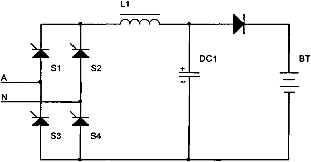
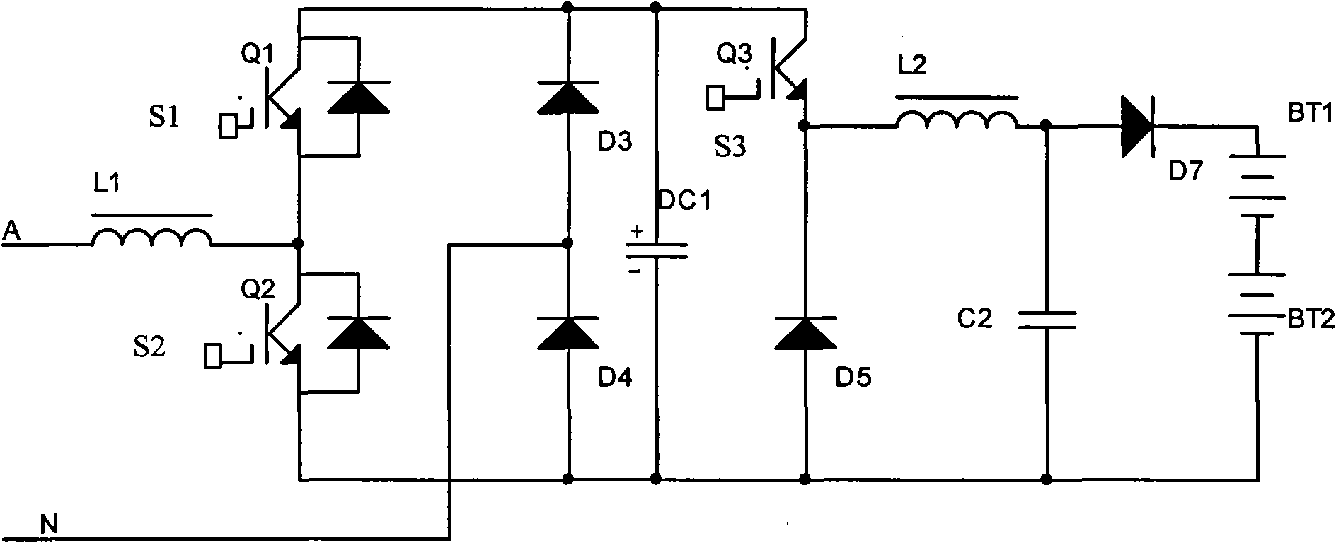
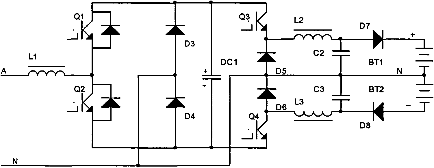
[0026] By cascading two step-up power factor correction circuits and step-down circuits, the present invention can realize the rectification of alternating current, adjust the output voltage range, and greatly reduce harmonic components.

[0027] The rectifier circuit provided by the present invention includes inductors L1, L2, first switching element Q1, second switching element Q2, third switching element Q3, diodes D3, D4, D5 and capacitors DC1, C2; wherein, one end of the inductor L1 is connected to the live wire The other end of the inductance L1 is also connected to the cathode of the diode D3, one end of the capacitor DC1, and one end of the third switching element Q3 through the first switching element Q1, and the other end of the inductor L1 is also connected to the diode D4 through the second switching element Q2. The anode, the other end of the capacitor DC1, and the anode of the diode D5 are connected, the anode of the diode D3 and the cathode of the diode D4 are co...


PUM


Abstract

The invention relates to a rectifier circuit, comprising two inductors L1 and L2, a first switch element Q1, a second switch element Q2, a third switch element Q3, three diodes D3, D4 and D5, and two capacitors DC1 and C2, wherein one end of the inductor L1 is connected with a fire wire and the other end thereof is connected with the cathode of the diode D3, one end of the capacitor DC1 and one end of the third switch element Q3 simultaneously by the first switch element Q2; the other end of the inductor L1 is connected with the anode of the diode D4, the other end of the capacitor DC1 and the anode of the diode D5 simultaneously by the second switch element; the anode of the diode D3 and the cathode of the diode D4 are connected with the zero line simultaneously; the cathode of the diode D5 is connected with the other end of the third switch element Q3; furthermore, the inductor L2 is connected in series with the capacitor C2 and is then connected in parallel to the diode D5. The rectifier circuit can greatly reduce the harmonic current and improve the circuit power factor; furthermore, compared with the output voltage, the input voltage can be output in a reducing or boosting way.

Description

technical field [0001] The invention relates to rectification technology, more specifically, to a rectification circuit. Background technique [0002] Electronic products cover all areas of human life, and when people use electronic products in daily life, they usually need to use direct current, and most of the power supply is alternating current. Therefore, in many places, it is necessary to convert alternating current into direct current, that is, to rectify alternating current. At present, the commonly used rectification circuit is a rectification bridge stack composed of four diodes, or a thyristor rectification and voltage regulation. see figure 1 , which is a circuit using thyristor rectification and voltage regulation in the prior art, and it utilizes the principle of phase-shifting voltage regulation. But these rectifier circuits usually have the following main disadvantages: 1. There are many harmonic components and large harmonic current, which will pollute the ...

Claims


Application Information

Patent Timeline
Patent Type & Authority Applications(China)
IPC IPC(8): H02M7/217
Inventor 魏晓亮
Owner SHENZHEN SINEXCEL ELECTRIC
Why Eureka
Try Eureka