Method for producing a discharge lamp, in particular a flat lamp

A technology of discharge lamps and discharge chambers, which is applied in the field of flat panel lamps, can solve problems such as labor-intensive and time-consuming removal, and achieve the effects of lower ignition voltage, high luminous efficiency, and good dimmability

Inactive Publication Date: 2009-11-18
OSRAM GMBH
View PDF1 Cites 0 Cited by
  • Summary
  • Abstract
  • Description
  • Claims
  • Application Information

AI Technical Summary

Problems solved by technology

[0004] Another important problem in the production of such panel lights is that the separate upper part and lower part are also exposed to conditions after removal of the luminescent material layer

Method used


Image

  • Method for producing a discharge lamp, in particular a flat lamp
  • Method for producing a discharge lamp, in particular a flat lamp
  • Method for producing a discharge lamp, in particular a flat lamp

Examples


Embodiment Construction

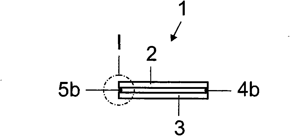
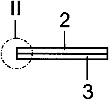
[0036] For producing a discharge lamp 1 designed as a panel lamp, a plate-shaped upper part 2 and a plate-shaped lower part 3 are provided. In this embodiment, the upper part 2 and the lower part 3 are constructed of glass material. The lower part 3 is designed as a rectangular plate, which is substantially planar. The upper part 2 can be constructed similarly to the lower part 3 . However, it can also preferably be provided that the upper part 2 has a corresponding rectangular shape to the lower part 3 and also includes a wave-shaped structuring in cross section.

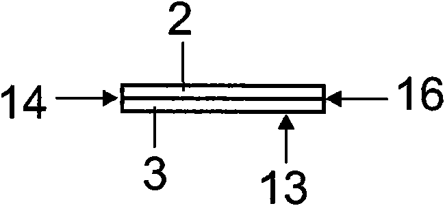
[0037] A layer of luminescent material is then applied to the surface of the upper part 2 and the lower part 3 respectively. It is also conceivable to additionally apply a reflective layer to the lower part. The upper part 2 and the lower part 3 are then introduced into a first device (not shown) in which the organic constituents of the phosphor paste of the phosphor layer are burned out by a heat treatment. Th...


PUM


Abstract

The invention relates to a method for producing a discharge lamp, comprising the following steps: a) a panel-type upper part (2) and a panel-type lower part (3) are provided, at least one region of the upper part (2) and/or the lower part (3) being made of a light-transmitting material; b) a luminescent layer (21, 31) is applied to one surface (2a, 3a) of the upper part (2) and/or the lower part (3); c) a plurality of spacer elements (4a, 4b, 5a, 5b) are placed between the upper part (2) and the lower part (3), said parts (2, 3) being interspaced in such a way that the luminescent layer (21, 31) faces the other part (2, 3); d) any incorporated water in or water deposits on the luminescent layer (21, 31) are removed by the creation of a gaseous stream (6), which flows between the upper part (2) and the lower part (3); e) a gas-tight connection is created on the continuous edge (13, 14, 15, 16) of the upper part (2) and the lower part (3).

Description

technical field [0001] The invention relates to a method for producing a discharge lamp, in particular a flat lamp. Background technique [0002] A panel lamp constructed as a discharge lamp is known by the applicant and is known, for example, as [0003] Furthermore, US 2006 / 0043857 A1 discloses a Hg-containing discharge lamp in the form of a panel lamp. The panel lamp includes a plate-shaped upper part and a plate-shaped lower part, which are connected to each other. A phosphor layer is respectively formed on the mutually facing surfaces of the two components. Both parts can be constructed as substantially flat plates. In particular, however, the upper part can also be designed as a plate-shaped part, which has a corrugated cross-section. This configuration makes it possible to form a plurality of discharge spaces arranged parallel to one another in the form of channels when connected together. At the edge, the upper part and the lower part are connected to each oth...

Claims


Application Information

Patent Timeline
IPC IPC(8): H01J9/39
CPCH01J9/268H01J9/39H01J9/227H01J9/26H01J61/36
Inventor 托马斯·诺尔
Owner OSRAM GMBH
Why Eureka
Try Eureka