Wave preventing system of hull and conveying pipeline of semi-submersible type sea thermal power station

A transmission pipeline and semi-submersible technology, which is applied in ocean energy power generation, transportation and packaging, special-purpose ships, etc., can solve problems such as water leakage at joints, swaying hulls, and poor static stability of hulls, so as to improve pressure resistance performance, reduce the wave receiving area, and improve the effect of wave resistance

Inactive Publication Date: 2009-11-25
郭芳声 +2
View PDF0 Cites 5 Cited by
  • Summary
  • Abstract
  • Description
  • Claims
  • Application Information

AI Technical Summary

Problems solved by technology

[0003] However, since the seawater temperature difference is only about 20°C, a large amount of seawater is required to achieve commercial-grade power generation. Therefore, the volume of the power generation ship and the diameter of the water delivery pipe are relatively large. However, if the power generation ship is in contact with the sea surface If the area is too large, the hull will be easily affected by wind and waves and shake, resulting in obviously poor static stability of the hull. Moreover, the existing water intake delivery pipe is combined with the hull in a fixed way, so when When the water intake delivery pipe is subjected to long-term stress and shaking due to the influence of the ocean current under the sea surface, the joint between the water intake delivery pipe and the hull will be easily damaged, or water leakage will be caused at the joint

Method used


Image

  • Wave preventing system of hull and conveying pipeline of semi-submersible type sea thermal power station
  • Wave preventing system of hull and conveying pipeline of semi-submersible type sea thermal power station
  • Wave preventing system of hull and conveying pipeline of semi-submersible type sea thermal power station

Examples


Embodiment Construction

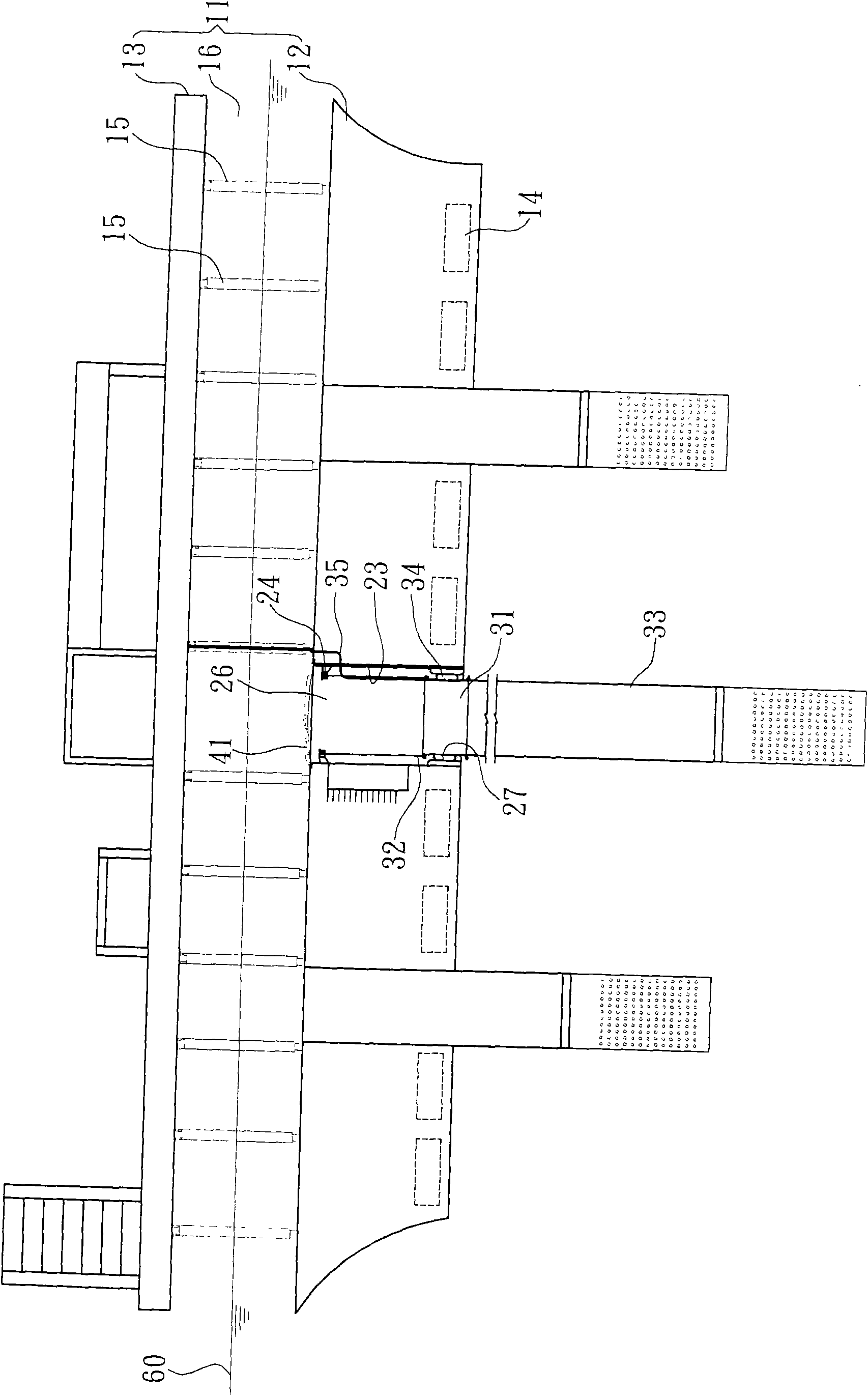
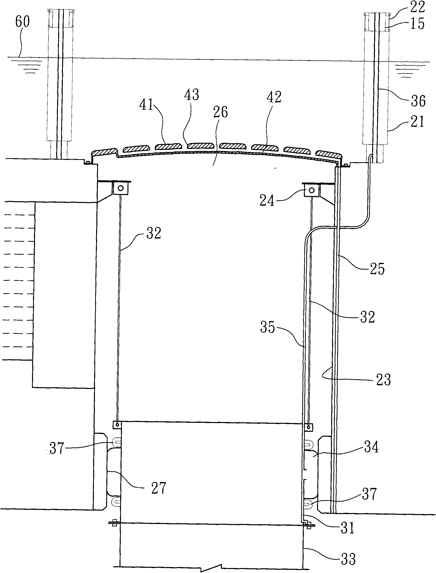
[0024] See first figure 1 , a semi-submersible ocean temperature difference power plant provided by the present invention has a hull and a wave avoidance system for the delivery pipeline, which is mainly composed of a hull 11, an annular joint 31 and a cover plate 41, wherein:

[0025] The hull 11, which can be driven or parked on the sea, has a bottom layer 12 and a deck layer 13, and several air chambers 14 are provided inside the bottom layer 12 of the hull 11, and each air chamber 14 can carry out a water inlet Or the action of draining water, whereby, when the air chambers 14 are filled with water, the hull 11 will sink due to the increase in load; conversely, when the air chambers 14 are drained, the hull 11 will be reduced due to the load And the buoyancy provided by the air chambers 14 greatly increases the buoyancy of the hull 11 and then reduces the draft of the hull 11 .

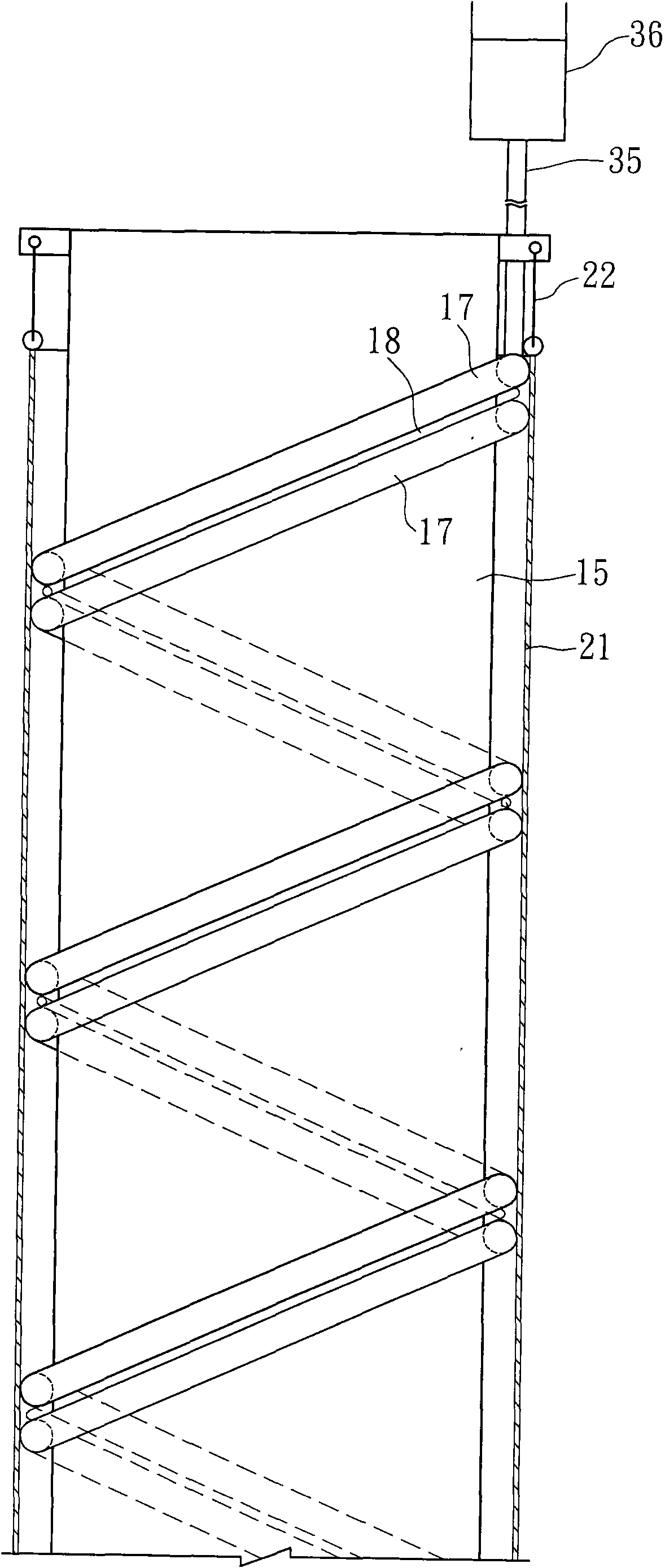
[0026] Furthermore, several support tubes 15 are provided between the bottom 12 of the hull 1...


PUM


Abstract

The invention relates to a wave preventing system for a hull and a conveying pipeline of a semi-submersible type sea thermal power station. A plurality of supporting pipes are arranged between a bottom layer and a deck layer of the hull so as to form a hollowed layer, and the bottom layer of the hull is provided with a through hole, an annular fastener and a cover plate, wherein the annular fastener is accommodated and arranged at the bottom of the through hole; the upper end of the annular fastener is provided with a plurality of pull rods which are upwards pivoted to the top edge of the through hole; the other end of the annular fastener is jointed with a conveying pipe; the outer edge of the annular fastener is annularly provided with a soft buffering piece, and the outer peripheral edge of the buffering piece is tightly jointed with a bottom opening of the through hole; the cover plate is used for sealing an upper opening of the through hole, internally provided with a wave damping channel and provided with a plurality of outward expanded open holes which are communicated with the wave damping channel.

Description

technical field [0001] The invention relates to the field of seawater temperature difference power generation, in particular to a semi-submersible ocean temperature difference power plant and a wave avoidance system for its hull and delivery pipeline. Background technique [0002] The principle of ocean thermal energy conversion is that after seawater absorbs solar heat energy, the surface seawater temperature is higher, while the deep seawater temperature is lower, and the temperature difference between the two is used to generate electricity. [0003] However, since the seawater temperature difference is only about 20°C, a large amount of seawater is required to achieve commercial-level power generation. Therefore, the volume of the power generation ship and the diameter of the water delivery pipe are relatively large. However, if the power generation ship is in contact with the sea surface If the area is too large, the hull will be easily affected by wind and waves and sh...

Claims


Application Information

Patent Timeline
Patent Type & Authority Applications(China)
IPC IPC(8): B63B35/00B63B3/00F03G7/05
CPCY02E10/34Y02E10/30
Inventor 郭芳声郭伯轩郭仲轩
Owner 郭芳声
Why Eureka
Try Eureka