
High-efficiency jet flow aeration device

An aeration device and high-efficiency jet technology, applied in sustainable biological treatment, water/sludge/sewage treatment, biological water/sewage treatment, etc., can solve the problem of increasing the floor area of ​​the aerobic treatment system and the effect of gas-liquid mass transfer Limited, high consumption and other problems, to achieve good aeration effect, reduce floor space and improve utilization rate

Inactive Publication Date: 2009-11-25
HAISIBOTE BEIJING SCIENE & TECH
View PDF0 Cites 2 Cited by
  • Summary
  • Abstract
  • Description
  • Claims
  • Application Information

AI Technical Summary

Problems solved by technology

[0002] Aeration equipment is an important factor affecting the effect of aerobic biochemical treatment. At present, aeration heads of various structures are mostly used. The aeration head is set at the bottom of the sewage treatment equipment, and the high-pressure air supply pipe is connected to shoot air out through the aeration head. In order to achieve the mixed mass transfer of air and sewage and achieve the effect of aeration, due to the pressure limitation of the air source, this kind of aeration equipment can only be used within 5 meters of water depth, and the water that is too deep will not be able to aerate. This also limits the depth of the aerobic biochemical pool and increases the floor area of ​​the aerobic treatment system. In addition, the gas-liquid mass transfer effect of this method of launching air jets into the sewage is limited, which requires a lot of energy and energy. high pressure air

Method used


Image

  • High-efficiency jet flow aeration device

Examples


Embodiment Construction

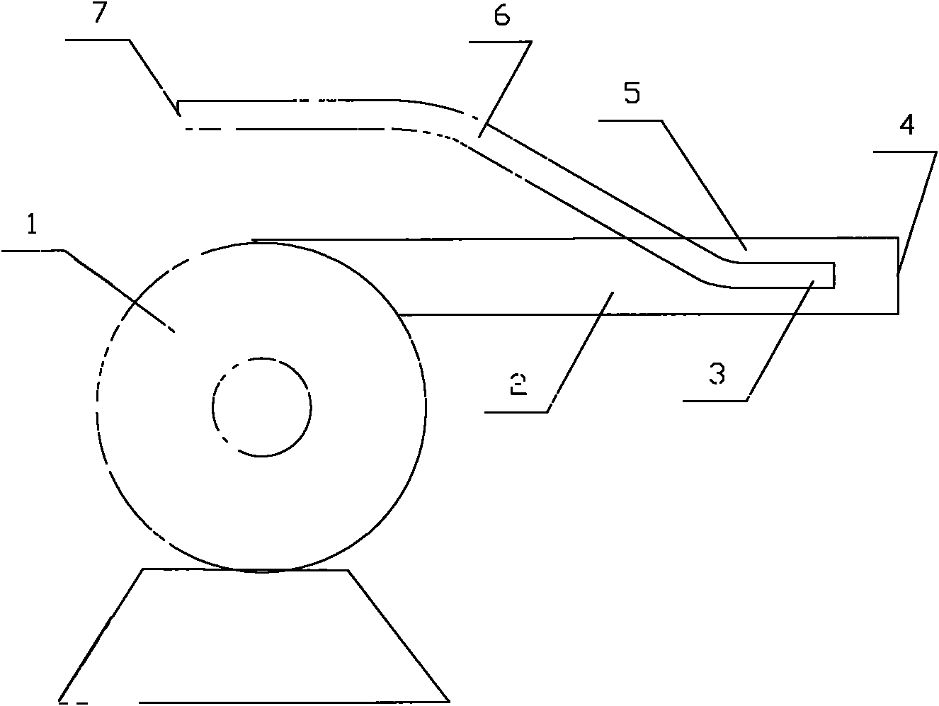
[0007] see figure 1 , the present invention relates to a high-efficiency jet aeration device, comprising a high-pressure water pump 1, a jet pipe 2 and several air pipes 6, the jet pipe is installed on the outlet of the high-pressure water pump to form an output pipeline of the high-pressure water pump, and the The front section 3 of each air tube is located in the jet tube, and its front end opening is located inside the front end opening of the jet tube.

[0008] The air tube is provided with an air inlet 7 outside the jet tube to allow air to enter during operation.

[0009] A part of the air tube is located inside the jet tube, and another part is located outside the jet tube.

[0010] The axis of the outlet end of the air tube overlaps with the axis of the corresponding position of the jet tube.

[0011] When there are multiple air pipes, each air pipe may be distributed along a circle, or one air pipe may be located in the middle, and the other air pipes may be distrib...


PUM


Abstract

The invention relates to a high-efficiency jet flow aeration device, which comprises a high-pressure water pump, a jet flow pipe and an air pipe, wherein the jet flow pipe is arranged on an outlet of the high-pressure water pump, and forms an output pipe of the high-pressure water pump; and the front end of the air pipe is positioned in the jet flow pipe, and a front end opening of the air pipe is positioned on the inner side of a front end opening of the jet flow pipe. When high-speed water flow is jetted from the jet flow pipe, a high negative-pressure zone is formed near the outlet of the air pipe, the air is sucked out of the air pipe and mixed with the water flow, and air molecules are violently bumped with water molecules in the high-speed flowing process to form a gas-liquid two-phase mixture, so that the mass transfer strength is greatly improved, and the good aeration effect is formed; because the jet flow is formed by the water pump, the jet flow formed in deeper water can be aerated, so that the water depth used in the invention is obviously deeper than that of the prior aeration head, and the water depth of the corresponding aerobic processing equipment is improved; and the jet flow can be processed twice in the same water, so that the floor area is reduced, and the utilization rate of the field is improved.

Description

technical field [0001] The invention relates to sewage treatment equipment, in particular to a high-efficiency jet aeration device, which belongs to the technical field of environmental protection. Background technique [0002] Aeration equipment is an important factor affecting the effect of aerobic biochemical treatment. At present, aeration heads of various structures are mostly used. The aeration head is set at the bottom of the sewage treatment equipment, and the high-pressure air supply pipe is connected to shoot air out through the aeration head. In order to achieve the mixed mass transfer of air and sewage and achieve the effect of aeration, due to the pressure limitation of the air source, this kind of aeration equipment can only be used within 5 meters of water depth, and the water that is too deep will not be able to aerate. This also limits the depth of the aerobic biochemical pool and increases the floor area of ​​the aerobic treatment system. In addition, the g...

Claims


Application Information

Patent Timeline
Patent Type & Authority Applications(China)
IPC IPC(8): C02F3/12
CPCY02W10/10
Inventor 陈光亮
Owner HAISIBOTE BEIJING SCIENE & TECH
Learn More