Method for fixing safe
A fixing method and technology for a safe, which can be applied to safes, luggage, buildings, etc., can solve the problems of complex and difficult to implement, easy to be stolen in the car safe, etc., and achieve the effect of fast fixing
- Summary
- Abstract
- Description
- Claims
- Application Information
AI Technical Summary
Problems solved by technology
Method used
Image
Examples
Embodiment 1
[0042] This embodiment includes the following steps:
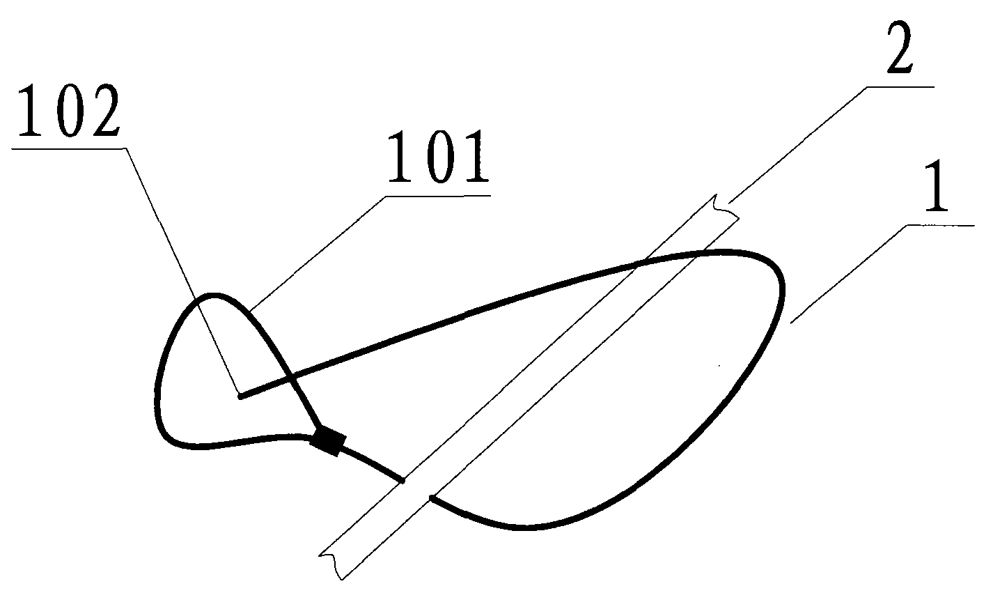
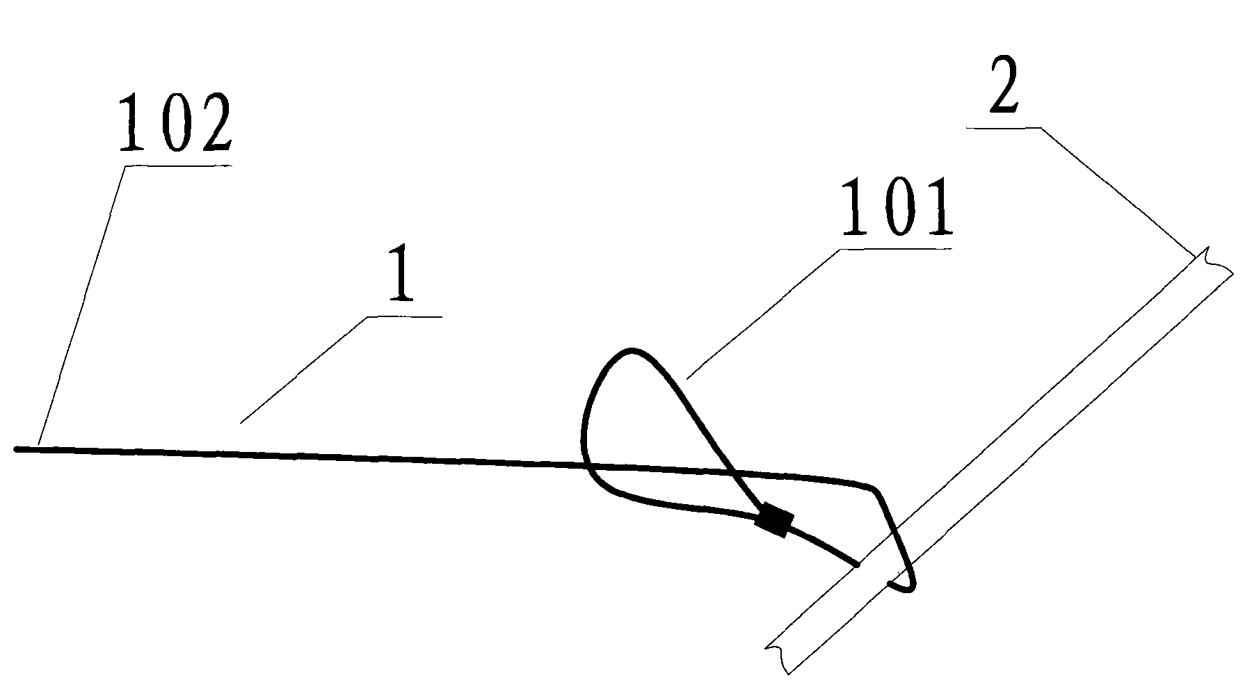
[0043] a) Wrap the first end of the metal rope and fix it on the car;
[0044] b) passing the second end of the metal rope through the hole on the wall of the vehicle safe box;
[0045] c) The second end of the metal rope is fixedly connected to the fixing part, and the fixing part cannot pass through the hole on the wall of the vehicle safe box.
[0046] The following is a step-by-step description:
[0047] a) Wrap the first end of the metal rope and fix it on the car
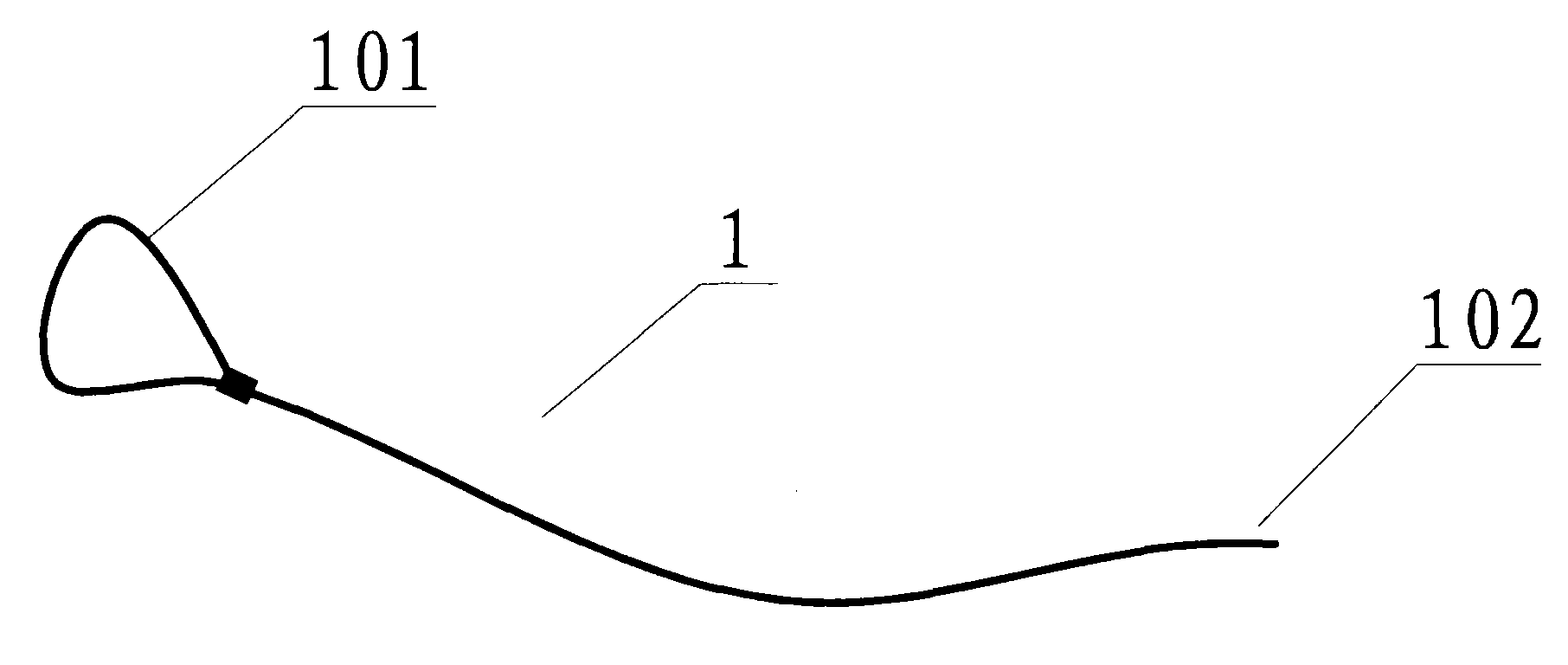
[0048] See figure 1 , figure 1 It is a schematic diagram of the metal rope used in this embodiment. The metal cord 1 has a first end 101 and a second end 102 . Wherein the first end 101 is ring-shaped. The formation of the ring structure of the first end 101 is relatively easy to realize. You can bend the metal rope and then clamp it with a metal clamp. The fixation here needs to be very firm and cannot be untied easily; otherwise , No matter how i...
Embodiment 2
[0063] The difference between this embodiment and Embodiment 1 lies in the way of fixed connection between the second end of the metal rope and the fixing member in step c).
[0064] First, a through hole 1024 is provided on the second end 102 of the metal cord. See Figure 13 , Figure 13 is a schematic diagram of the second end of the metal rope in this embodiment.
[0065] Then, pass the second end 102 of the metal rope through the hole 4 on the wall 3 of the vehicle safe box, and enter the interior of the vehicle safe 3 . Such as Figure 14 shown.
[0066] Finally, a common lock 9 is used to lock the through hole 1024 on the second end of the metal cord, such as Figure 15 as shown, Figure 15 after locking Figure 14 Schematic diagram of direction A-A in the figure. When the lock is fixedly connected to the second end of the metal rope, the size of the fixing piece in any direction is not required to be larger than the size of the hole on the wall of the vehicle-m...
Embodiment 3
[0068] The difference between embodiment 3 and embodiment 1 is that there is a soft layer of non-metal material on the outside of the metal rope. The soft layer of non-metal material can be a cloth layer or a rubber layer. The hardness of metal is high. It is easy to cause injury to people during the process, and the friction is small. After using the cloth layer or rubber layer, it is easy to touch because of its low hardness, and it also reduces unnecessary injuries. In addition, the cloth layer or rubber layer and other substances When in contact, the coefficient of friction is greater and easier to operate.
PUM
 Abstract
Description
Claims
Application Information
 - R&D
- Intellectual Property
- Life Sciences
- Materials
- Tech Scout
- Unparalleled Data Quality
- Higher Quality Content
- 60% Fewer Hallucinations
Browse by: Latest US Patents, China's latest patents, Technical Efficacy Thesaurus, Application Domain, Technology Topic, Popular Technical Reports.
© 2025 PatSnap. All rights reserved.Legal|Privacy policy|Modern Slavery Act Transparency Statement|Sitemap|About US| Contact US: help@patsnap.com


