Laminated intelligent shock-isolation bearing capable of self-adaptively regulating cutting performance

A technology of self-adaptive adjustment and shock-isolation bearings, which is applied in the field of structural shock-isolation, can solve problems affecting the performance of the intelligent composite shock-isolation system, damage to the shock-isolation structure, etc. The effect of small displacement and high safety

Inactive Publication Date: 2009-11-25
WUHAN UNIV OF TECH
0 Cites 29 Cited by

AI-Extracted Technical Summary

Problems solved by technology

However, near-fault earthquake motions input high energy into the structure at the beginning of the earthquake, and the settlement of the magnetorheological fluid material in the magnetorheological fluid smart damper greatly affects the performance of the in...

Method used

[0023] The large deformation soft magnetic material 7 can be soft magnetic alloy, deformable permanent magnetic alloy. These materials not only have high magnetic permeability and saturation magnetic induction, but also have strong elastic-plastic properties, even if a large shear deformation occurs, their magnetic permeability will not be affected. The large deformation soft magnetic material 7 can be installed between the upper connecting plate 1 or the lower connecting plate 4 and the permeable core 6 .
[0024] The upper connection plate 1, the lower connection plate 4, the magnetic steel plate 3, and the magnetic core 6 are all made of magnetic materials (silicon steel, magnetic alloy, low carbon steel). The thickness of the connection plate and the magnetic steel plate, the width (diameter) of the magnetic core and the thi...

Abstract

The invention relates to a laminated intelligent shock-isolation bearing capable of self-adaptively regulating cutting performance, the bearing is mainly composed of a magnetic assembly, a sensor (8) and a controller (9), wherein, the magnetic assembly is composed of magnetorheological elastomers (2) which are alternatively overlapped together, have the same shape and are sulfurized as a whole, a magnetically-conducting steel plate (3) and a coil winding (5) which is separated from the magnetorheological elastomers and is wound on a magnetically-conducting iron core (6), all of them are mounted between an upper connecting plate and a lower connecting plate to thereby form a complete closed magnetic circuit; a large deformation soft magnetic material (7) is arranged in the middle of the magnetic circuit; the sensor is mounted on the top of the upper connecting plate (1) and the controller is connected with the sensor and the coil winding via data lines, respectively. The invention can self-adaptively regulates the cutting performance thereof in accordance with external response; compared with ordinary rubber shock-isolation bearing, the bearing has small displacement among shock-isolation layers and strong controllability; and compared with intelligent complex shock-isolation system, the bearing has simple structure and good stability.

Application Domain

Technology Topic

Image

  • Laminated intelligent shock-isolation bearing capable of self-adaptively regulating cutting performance
  • Laminated intelligent shock-isolation bearing capable of self-adaptively regulating cutting performance
  • Laminated intelligent shock-isolation bearing capable of self-adaptively regulating cutting performance

Examples

  • Experimental program(1)

Example Embodiment

[0018] The present invention will be further described below in conjunction with the embodiments and drawings, but the present invention is not limited.
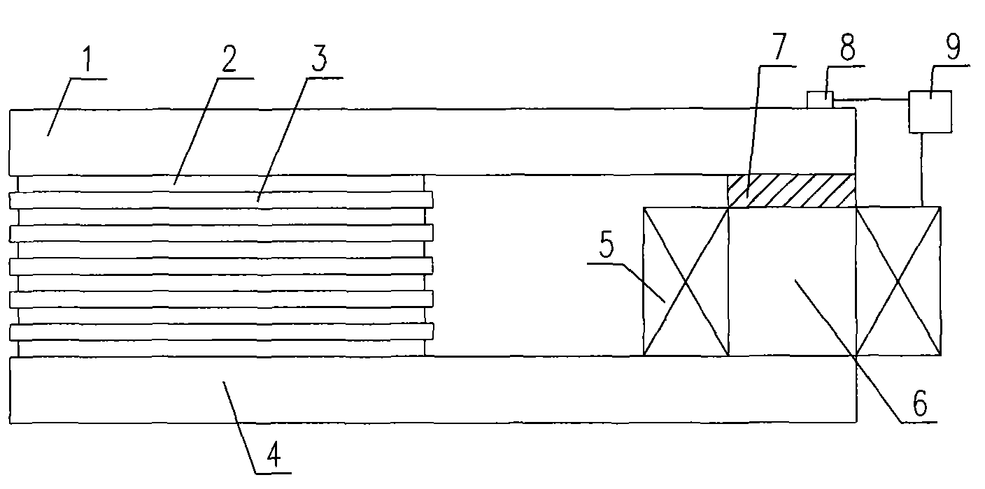
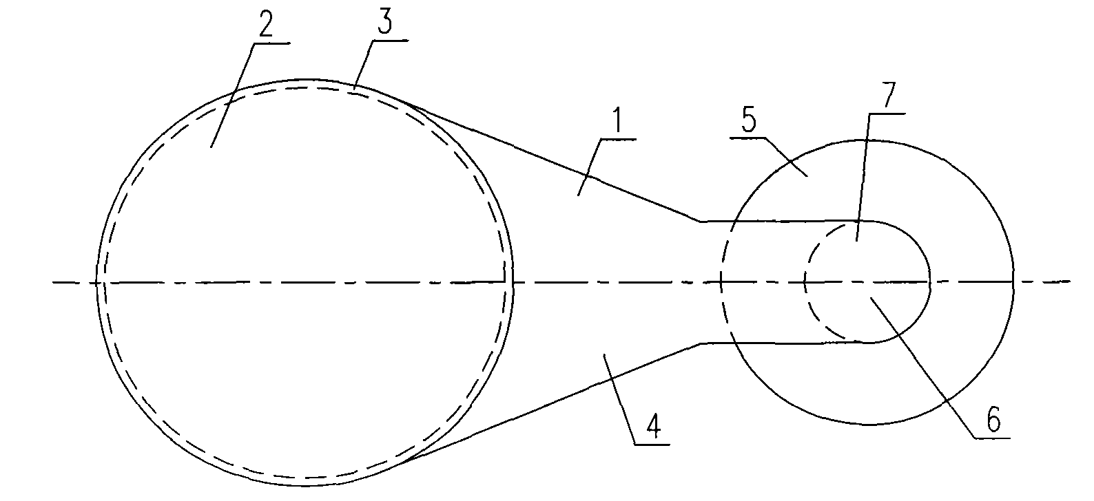
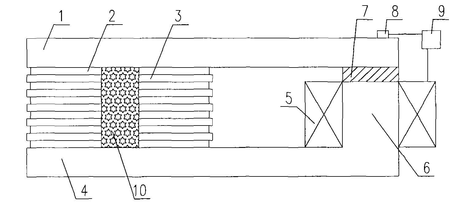
[0019] The laminated intelligent vibration isolation support (referred to as the intelligent vibration isolation support) provided by the present invention for adaptively adjusting the shear performance has a structure such as Figure 1 to Figure 2 Shown: Mainly composed of magnetic components, sensor 8 and controller 9. Among them: the magnetic components are composed of magnetorheological elastomers 2, magnetic steel plates 3, which are alternately stacked together, have the same shape and are vulcanized, and are separated from the magnetorheological elastomers 2 and wound on the magnet core 6 The coil winding 5 is composed of these components installed between the upper and lower connecting plates, thereby forming a complete closed magnetic circuit; a large deformation soft magnetic material 7 is arranged in the middle of the magnetic circuit; the sensor 8 is installed on the upper connecting plate 1 At the top, the controller 9 is respectively connected to the sensor 8 and the coil winding 5 through data lines. figure 2 Mainly shows the shape of the seismic isolation support, so the sensor 8 and the controller 9 are not shown.
[0020] In order to coordinate the deformation between the magnetorheological elastomer 2 and the magnetic steel plate 3, vulcanization treatment is required between them to enhance the adhesion between the elastomer and the steel plate.
[0021] The shapes of the magnetorheological elastic body 2 and the magnetic steel plate 3 are round, rectangular or other shapes (such as ellipse), so that the intelligent seismic isolation support is made into a round, rectangular or other shape (such as ellipse). Shape) to meet the installation requirements of seismic isolation buildings. The magnetorheological elastomer may be other rheological smart materials (such as electrorheological elastomers, etc.). After the smart material is changed, the size of the structure needs to be recalculated and analyzed, and the corresponding circuit material will change, but the structure form remains unchanged.
[0022] The magnetorheological elastomer 2 is a new branch of magnetorheological materials. It is composed of natural rubber or silicone rubber matrix and magnetic particles. The rubber mixed with magnetic particles is cured under the action of an external magnetic field. The magnetorheological effect (that is, the magnetic particles form a chain-like aggregation structure in the direction of the magnetic field) makes the particles in the rubber matrix. In order to form an ordered structure. This ordered structure after curing greatly increases the storage modulus of the magnetorheological elastomer. When the external magnetic field is removed, the storage modulus of the material returns to normal, that is, the mechanical properties of the magnetorheological elastomer can be Controlled by the magnetic field. We can adjust the shear performance of the seismic isolation support by changing the magnetic induction intensity to control the mechanical properties of the magnetorheological elastomer 2 to form a smart isolation support with adjustable horizontal equivalent stiffness and equivalent damping ratio.
[0023] The large deformation soft magnetic material 7 can be a soft magnetic alloy or a deformable permanent magnetic alloy. These materials have high magnetic permeability and saturation magnetic induction, but also have strong elastoplastic properties, even if they produce large shear deformation, their magnetic permeability will not be affected. The large deformation soft magnetic material 7 can be installed between the upper connecting plate 1 or the lower connecting plate 4 and the magnetic conductor core 6.
[0024] The upper connecting plate 1, the lower connecting plate 4, the magnetically conductive steel plate 3, and the magnetically conductive core 6 are all made of magnetically conductive materials (silicon steel, magnetic alloy, low carbon steel). The thickness of the connecting plate and the magnetic conductive steel plate, the width (diameter) of the magnetic conductive core and the thickness of the magnetorheological elastomer should be optimized by the magnetic field finite element analysis to make the magnetic induction intensity of the magnetorheological elastomer to reach maximum.
[0025] In order to enhance the damping characteristics of the intelligent seismic isolation support, the present invention is also provided with a lead core 10, which is mounted on the central part of the magnetorheological elastic body 2 and the magnetic conductive steel plate 3, such as Figure 3 to Figure 4 Shown. The lead core is coaxial with the magnetorheological elastic body 2 and the magnetically conductive steel plate 3, and has the same shape, and its side length (diameter) is determined according to the actual situation. After adding the lead core, the magnetic circuit analysis of the intelligent seismic isolation support needs to re-calculate the magnetic field finite element. Figure 4 Mainly shows the shape of the seismic isolation support and the position of the lead core 10, so the sensor 8 and the controller 9 are not shown.
[0026] The magnetic line of force of the intelligent vibration isolation support of the present invention is as follows Figure 5 to Figure 6 Shown: the coil winding excites the magnetic field, and the conductive core can enhance the magnetic induction intensity. The magnetic line of force starts from the iron core 10, passes through the large deformation soft magnetic material 7, the upper connecting plate 1, the magnetorheological elastomer 2, the magnetic steel plate 3, the lower connecting plate 4, and finally returns to the iron core 10 to form a complete closed magnetic circuit .
[0027] In the present invention, a set of coil windings 5 ​​can excite the magnetic field, or multiple sets of parallel coil windings 5 ​​can excite the magnetic field. Figure 6 The magnetic field lines of two sets of parallel coil windings are shown. The magnetic field lines of the two sets of coils must follow the right-hand rule. For multiple sets of coil windings, the magnetic line of force must also follow the right-hand rule.
[0028] The working process of the present invention is briefly described below.
[0029] First, the sensor 8 is used to sense the effect of external power. The sensor inputs the power response signal to the controller 9. The controller will send a control signal according to the corresponding control strategy to change the current in the coil winding 5, thereby changing the elasticity of the magnetorheological fluid. The magnetic flux density of body 2.
[0030] When an earthquake strikes, the support will vibrate violently to cause a relatively large horizontal relative displacement between the upper connecting plate 1 and the lower connecting plate 4, and this relative displacement will destroy the coil winding 5 and make the magnetic field of the entire support invalid. In order to ensure that the coil winding 5 and the conductor core 6 do not deform under severe vibration, we install a large-deformation soft magnetic material 7 between the upper connecting plate 1 (or the lower connecting plate 4) and the conductor core 6. The large deformed soft magnetic material 7 will vibrate together with the upper and lower connecting plates, thereby protecting the stability of the coil winding 5.

PUM

no PUM

Description & Claims & Application Information

We can also present the details of the Description, Claims and Application information to help users get a comprehensive understanding of the technical details of the patent, such as background art, summary of invention, brief description of drawings, description of embodiments, and other original content. On the other hand, users can also determine the specific scope of protection of the technology through the list of claims; as well as understand the changes in the life cycle of the technology with the presentation of the patent timeline. Login to view more.

Similar technology patents

Classification and recommendation of technical efficacy words

Why Eureka
Try Eureka