Method for correcting deviation of depth measuring sonar system

A system deviation, sounding sonar technology, applied in the field of sounding sonar, can solve the problems of multi-channel inconsistency, incident angle system deviation, etc.

Inactive Publication Date: 2009-11-25
INST OF ACOUSTICS CHINESE ACAD OF SCI
View PDF0 Cites 22 Cited by
  • Summary
  • Abstract
  • Description
  • Claims
  • Application Information

AI Technical Summary

Problems solved by technology

[0009] The above-mentioned method has the following deficiencies and defects: 1) The above-mentioned system deviation correction method, in essence, hopes to reduce the influence of other parameters as much as possible, and highlights the influence of the parameters to be corrected for deviation correction
But in fact, the sounding error is the result of the comprehensive influence of various parameters, so a single system deviation correction method can only remove the significant system deviation influence to a certain extent
2) The above-mentioned system deviation correction method is based on multi-beam sounding sonar, and does not take into account the characteristics of other sounding sonars. For example, high-resolution sounding side-scan sonar has the following characteristics: First, high-resolution The main estimation parameter of depth-sounding side-scan sonar is the direction of arrival of the echo; second, high-resolution sounding side-scan sonar generally does not use beam stabilization technology; It will cause systematic deviation in calculating the angle of incidence; Fourth, the high-resolution sounding side-scan sonar adopts a sonar array on the left and right sides, and two sets of independent sonar array installation parameters are required.
Therefore, the existing system deviation correction method is difficult to be directly used in high-resolution bathymetric side-scan sonar

Method used


Image

  • Method for correcting deviation of depth measuring sonar system
  • Method for correcting deviation of depth measuring sonar system
  • Method for correcting deviation of depth measuring sonar system

Examples


Embodiment 1

[0053] After the high-resolution bathymetric side-scan sonar obtains the incident angle and time delay, it also needs to use various sensors to obtain carrier position, carrier attitude, sound velocity profile, tide level and other data, as well as sonar arrays and various sensors on the carrier. The spatial position relationship data of the obtained time delay and incident angle are corrected, and finally the latitude and longitude coordinates and steady-state depth of the measured seabed are derived. Table 1 is a list of the main parameters affecting the error of high-resolution bathymetric side-scan sonar.

[0054] Table 1

[0055] parameters

Depth of influence

Affected position

Incidence angle θ

yes

yes

Delay τ

yes

yes

Roll (R)

yes

yes

Trim (P)

yes

yes

First shake (H)

no

yes

speed of sound (c)

yes

yes

...

Embodiment 2

[0069] Steps 1 to 3 and Steps 5 and 6 of this embodiment are consistent with Embodiment 1, the difference is that in order to obtain more accurate deviation correction data, Step 4 of this embodiment takes into account the incidence caused by the inconsistency of the sonar channel Angle system deviation, which corrects both roll and incident angle deviation. The principle and implementation steps of Step 4 of this embodiment will be described in detail below.

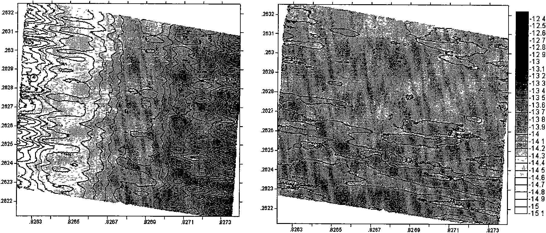
[0070] For high-resolution bathymetric side-scan sonar, due to the inconsistency between channels, the incident angle obtained after signal processing has a fixed deviation. Its size changes with the value of θ, and it will have a larger value when the value of θ is in a certain range. This deviation appears on the bathymetric chart as a ditch-like or ridge-like pseudo-terrain parallel to the track direction. Due to the existence of incident angle deviation, the calculation of the average slope in the vertical track d...

Embodiment 3

[0083] This embodiment is based on Embodiment 2, and further considers the output delay of the motion sensor, so as to perform more accurate correction of each system deviation.

[0084] In addition to installation deviations, roll, pitch and yaw angles also have deviations caused by motion sensor output delays. This deviation can be corrected by using a certain method to obtain the output delay of the motion sensor. Generally, the output delay of the motion sensor is a fixed system parameter, which is given by the motion sensor manufacturer. However, in actual work, due to the delay of data transmission or computer processing data, the actual output delay of the motion sensor does not match the value given by the manufacturer. The measurement of this value is relatively difficult. In this paper, the output delay correction of the motion sensor is performed through data post-processing. The principle is that it can be proved geometrically that the slope of a certain frame is ...


PUM


Abstract

The invention provides a correcting method for the deviation of a depth measuring sonar system, which comprises the following steps: 1) acquiring data by a sea calibration test to obtain initial values of various parameters to be calibrated; 2) selecting a parameter to be calibrated and calculating correction quantity of the selected parameter to be calibrated according to current values of various parameters to be calibrated; and 3) judging whether the current correction quantity of the selected parameter to be calibrated is less than a preset threshold value or converged into certain value or not, if the judging result is not, substituting the value of the parameter to be calibrated by the sum of the current value of the parameter to be calibrated and the current correction quantity, and returning the step 2) until all correction quantity of the parameter to be calibrated accord with the judging conditions. With the correcting method, various calibration parameters of the system are comprehensively considered, the influence of the deviation of various systems is reduced by using a feedback mechanism and the accuracy of the deviation correction quantity of various systems is improved. Meanwhile, with the correcting method, various characteristic of a high resolution depth measuring side scanning sonar are considered, so the correcting method is particularly suitable to be applied to the high resolution depth measuring side scanning sonar.

Description

technical field [0001] The invention belongs to the technical field of sounding sonar, in particular, the invention relates to a deviation correction method of a sounding sonar system. Background technique [0002] At present, there are three types of sounding sonars commonly used, one is multi-beam sounding system, the other is high-resolution sounding side-scan sonar, and the third is interferometric synthetic aperture sonar. The multi-beam bathymetric system appeared earlier and has a wider range of applications; the high-resolution bathymetric side-scan sonar appeared later and is currently in the process of promotion; the interferometric synthetic aperture sonar system is the most complex and is currently in the process of development. Therefore, the following mainly introduces the first two types of sounding sonar. [0003] A high-resolution bathymetric side-scan sonar is an acoustic device capable of detecting seafloor topography and landforms in high resolution. It...

Claims


Application Information

Patent Timeline
Patent Type & Authority Applications(China)
IPC IPC(8): G01S7/52G01S15/08G01S15/89
Inventor 刘晓东朱维庆高俊涛张方生孙宇佳
Owner INST OF ACOUSTICS CHINESE ACAD OF SCI
Why Eureka
Try Eureka