AI technical title is built by PatSnap AI team. It summarizes the technical point description of the patent document.
A photon sieve and large-area technology, applied in the field of photon sieves, can solve problems such as difficulty in increasing the diameter of photon sieves
Inactive Publication Date: 2010-07-21
SUZHOU UNIV
View PDF3 Cites 0 Cited by
Summary
Abstract
Description
Claims
Application Information
AI Technical Summary
This helps you quickly interpret patents by identifying the three key elements:
Problems solved by technology
Method used
Benefits of technology
Problems solved by technology
[0004] The purpose of the present invention is to provide a photon sieve with a new structure, which adopts a partition design method to increase the diameter of the minimum aperture of the photon sieve and break through the limit of the minimum aperture in the manufacturing process, thereby solving the problem that it is difficult to increase the diameter of the photon sieve in the prior art. Realize the preparation of large-area photonic sieves
Method used
Image
Click on the blue label to locate the original text in one second.
Reading with bidirectional positioning of images and text.
Examples
Embodiment 1
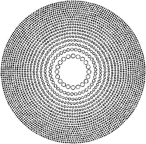
[0038] Embodiment 1: A photon sieve with a new structure, diameter Φ=100mm, focal length f=500mm, working wavelength λ=632.8nm.
[0039] If the design method of the traditional photon sieve is adopted, the photon sieve required by this embodiment will have a period of 3940 rings, and the minimum aperture diameter will be 0.00318mm, such as image 3 shown. These parameters clearly pose a great challenge to current manufacturing processes.
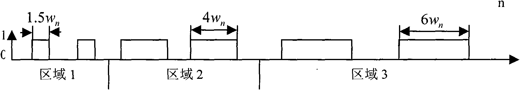
[0040] This example figure 2 As shown, the photon sieve is divided into three regions,
[0041]
[0042] in w n = λf 2 r n is the small hole diameter of the photon sieve before merging (the small hole diameters of the three regions are respectively enlarged to 1.5, 4, and 6 times of the original), λ is the working wavelength, f is the focal length of the new photon sieve, f n is the distance from the ce...
Embodiment 2
[0049] For a photon sieve with f=500mm, D=50mm, and λ=632.8nm, the design scheme of the photon sieve of the present invention is adopted. Using the Gaussian density modulation function, after calculation, m=987 rings are divided into 3 areas, the number of rings after partitioning is 159, and the merging periods are 3, 5, and 8 respectively, as shown in the table below
[0050]
[0051] After optimization, σ f = 1.505, μ = 0, c = 0.8 and h = 2.75
[0052] With the new design scheme, the minimum hole diameter is changed from 63.28um to 279.07um.
Embodiment 3
[0054] For the photon sieve with f=500mm, D=50mm, λ=405nm, we use a new photon sieve design scheme. Using the Weber density modulation function, after calculation, m=1542 rings are divided into 4 areas, the number of rings after partitioning is 219, and the merging periods are 3, 5, 8, and 10 respectively, as shown in the table below
[0055]
[0056] In this embodiment, the density function is a Weibull function,
[0057] f ( r n ) = c α β f ( r n h · β f ) α - 1 e - ( ...
PUM
Property
Measurement
Unit
diameter
aaaaa
aaaaa
Abstract
The invention discloses a large area photonsieve composed of sheets with girdle band holes and characterized in that the girdle band is divided into G regions from the inner portion to the outer portion along the radius direction of the photonsieve. The regions are combined relative to the girdle band of the Phase Fresnel zone plate so as to correspondingly enhance the correspondent hole radius.The hole distribution number on each girdle band is optimized. The large area photonsieve is divided into a plurality of regions by knowing the imaging mechanism. The hole diameter in each region isamplified to a scale. Furthermore, the hole diameter of the photon sieve, especially the peripheral hole dimension is amplified by combining the girdle bands so as to basically improve the resolutionof the optical system.
Description
technical field [0001] The invention relates to an optical device, in particular to a large-area photon sieve for optical diffraction imaging. Background technique [0002] Photon sieve imaging is a new imaging method developed in recent years. The photon sieve is an optical diffraction device based on the traditional Fresnel zone plate, which replaces the transparent annulus in the zone plate with a large number of small holes. Photonic sieves have the characteristics of small size, light weight, and the spectral range can cover soft X-rays, extreme ultraviolet, etc., and these are the spectral regions that are difficult to achieve with traditional refractive or reflective optical devices. Photonic sieves have attracted extensive attention in recent years due to their broad application prospects in aerospace, astronomical observation, extreme ultravioletlithography, physics and life sciences. Photonic sieves were first invented by Kipp et al. in 2001 based on Fresnel zon...
Claims
Application Information
Patent Timeline
Application Date:The date an application was filed.
Publication Date:The date a patent or application was officially published.
First Publication Date:The earliest publication date of a patent with the same application number.
Issue Date:Publication date of the patent grant document.
PCT Entry Date:The Entry date of PCT National Phase.
Estimated Expiry Date:The statutory expiry date of a patent right according to the Patent Law, and it is the longest term of protection that the patent right can achieve without the termination of the patent right due to other reasons(Term extension factor has been taken into account ).
Invalid Date:Actual expiry date is based on effective date or publication date of legal transaction data of invalid patent.

