Laser repair device with automatic detection function

A laser repair and automatic detection technology, applied in laser welding equipment, optics, manufacturing tools, etc., can solve the problems of misjudgment of image detection, inability to effectively reduce operation time, etc., and achieve the effect of accurate detection

Inactive Publication Date: 2009-11-25
CONTREL TECH CO LTD
View PDF0 Cites 6 Cited by
  • Summary
  • Abstract
  • Description
  • Claims
  • Application Information

AI Technical Summary

Problems solved by technology

[0003] Even though the existing technology uses an optical detection module to achieve automatic judgment during inspection, after the panel judgment is completed, the panel still needs to be moved to the laser device for repair, and then moved back to the inspection device for re-judgment after the repair is completed. Unable to effectively reduce the overall operating time
[0004] Additionally, if figure 1 As shown, the exi

Method used


Image

  • Laser repair device with automatic detection function
  • Laser repair device with automatic detection function
  • Laser repair device with automatic detection function

Examples


Embodiment Construction

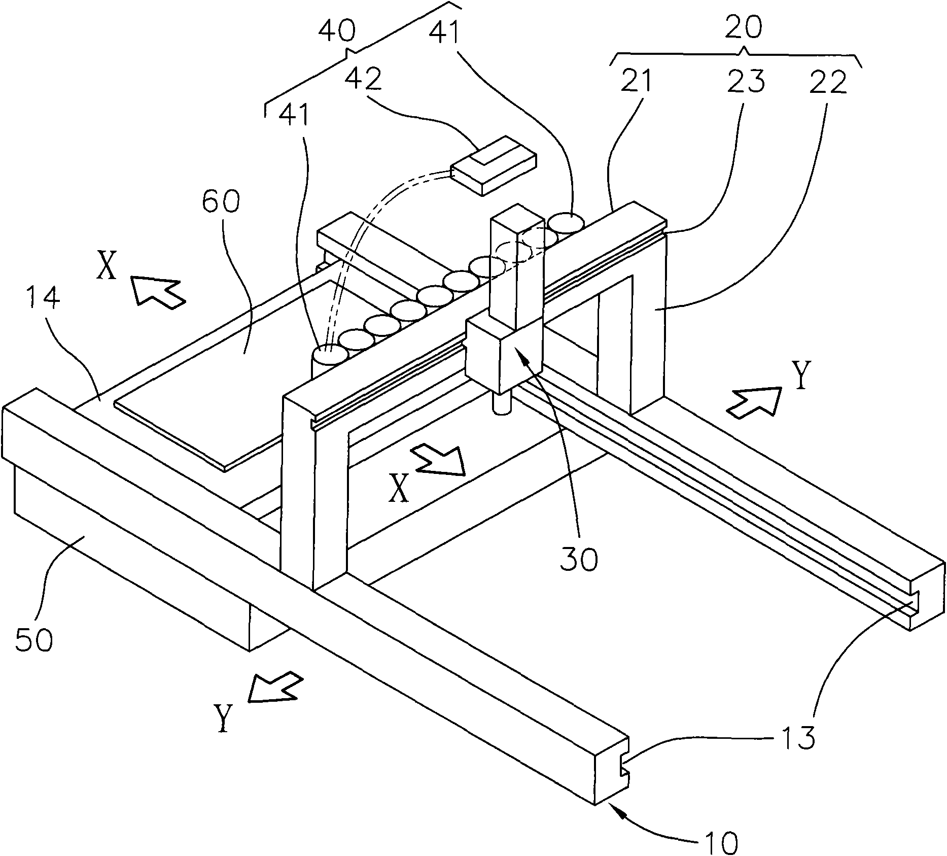
[0039] Such as image 3 and Figure 4 As shown, the present invention is a laser repair device with automatic detection function, which includes:

[0040] A base 10 has a planar work area 11, a pair of first rails 13 and a movable part 14; the planar work area 11 has a detection work part 11A and a repair work part 11B, and the moveable part 14 is used to place Put an object to be tested 60, and the movable part 14 is arranged on the first track 13 in a sliding manner, and can move in a first axial direction X on the first track 13, thereby, the object to be tested 60 is to use the movable part 14 to achieve movement, and the range of movement is between the inspection work part 11A and the repair work part 11B;

[0041] A support part 20 is located on the base 10 and is between the detection work part 11A and the repair work part 11B; the support part 20 has a first surface 21, a second surface 22 and a the second track 23 of the second surface 22;

[0042] A laser device...


PUM


Abstract

The invention relates to a laser repair device with an automatic detection function, which comprises a base, a bracket part, a laser device, a detection lens group and a backlight box, wherein the base is provided with a detection working part which corresponds to the detection lens group, a repair working part which corresponds to the laser device and a moving part which is used for placing an object to be detected and can do a first axial movement; the laser device can do a second axial movement on the bracket part; a plurality of lenses of the detection lens group are used for capturing images, and an overlay image processing module is used for processing retrieved image overlap; and during repair, the first axial movement of the moving part and the second axial movement of the laser device are utilized to repair a dead pixel position. The laser repair device has the advantages and the effects of convenient use, time saving, precise detection, automation detection, and the like.

Description

technical field [0001] The present invention relates to a laser repair device with an automatic detection function, in particular to a laser repair device with an automatic detection function with an overlapping image processing module, which has the advantages of convenient use, time saving, accurate detection and automatic detection. and efficacy. Background technique [0002] Existing detection devices only have the function of image detection (scanning or interception), and the laser device is used for repair or distance measurement. In the past, after the panel manufacturing process is completed, the liquid crystal panel will be inspected with an inspection device (such as a lighting machine), and after recording the defective points, the panel will be moved to the laser device for repairing the damaged points; Moving the panel from the laser device back to the detection device for re-judgment adds many procedures such as transportation, calibration, positioning, etc.,...

Claims


Application Information

Patent Timeline
IPC IPC(8): G02F1/13B23K26/00
Inventor 萧贤德王正宇田孝通
Owner CONTREL TECH CO LTD
Why Eureka
Try Eureka