Planar waveguide sum-and-difference network

A planar waveguide and network technology, applied in waveguides, waveguide-type devices, electrical components, etc., can solve the problems of inability to meet high power requirements and large losses in the form of microstrips, and achieve compact structure, wide bandwidth, and high efficiency.

Inactive Publication Date: 2009-11-25
BEIJING HUADA ZHIBAO ELECTRONICS SYST
View PDF0 Cites 9 Cited by
  • Summary
  • Abstract
  • Description
  • Claims
  • Application Information

AI Technical Summary

Problems solved by technology

In the sum-difference network of the planar structure, the sum-difference network of the microstrip form cannot meet the requirements of high power, and for large arrays, the loss of the microstrip form becomes an irreparable defect

Method used


Image

  • Planar waveguide sum-and-difference network
  • Planar waveguide sum-and-difference network
  • Planar waveguide sum-and-difference network

Examples


Embodiment Construction

[0031] The present invention will be described in detail below through specific embodiments and accompanying drawings.

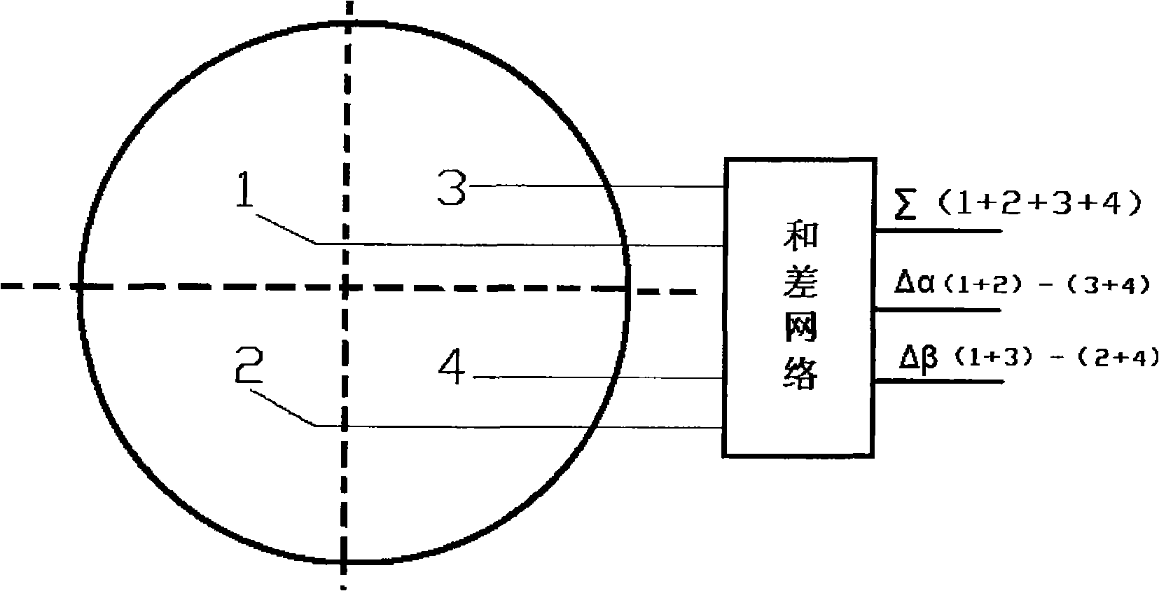
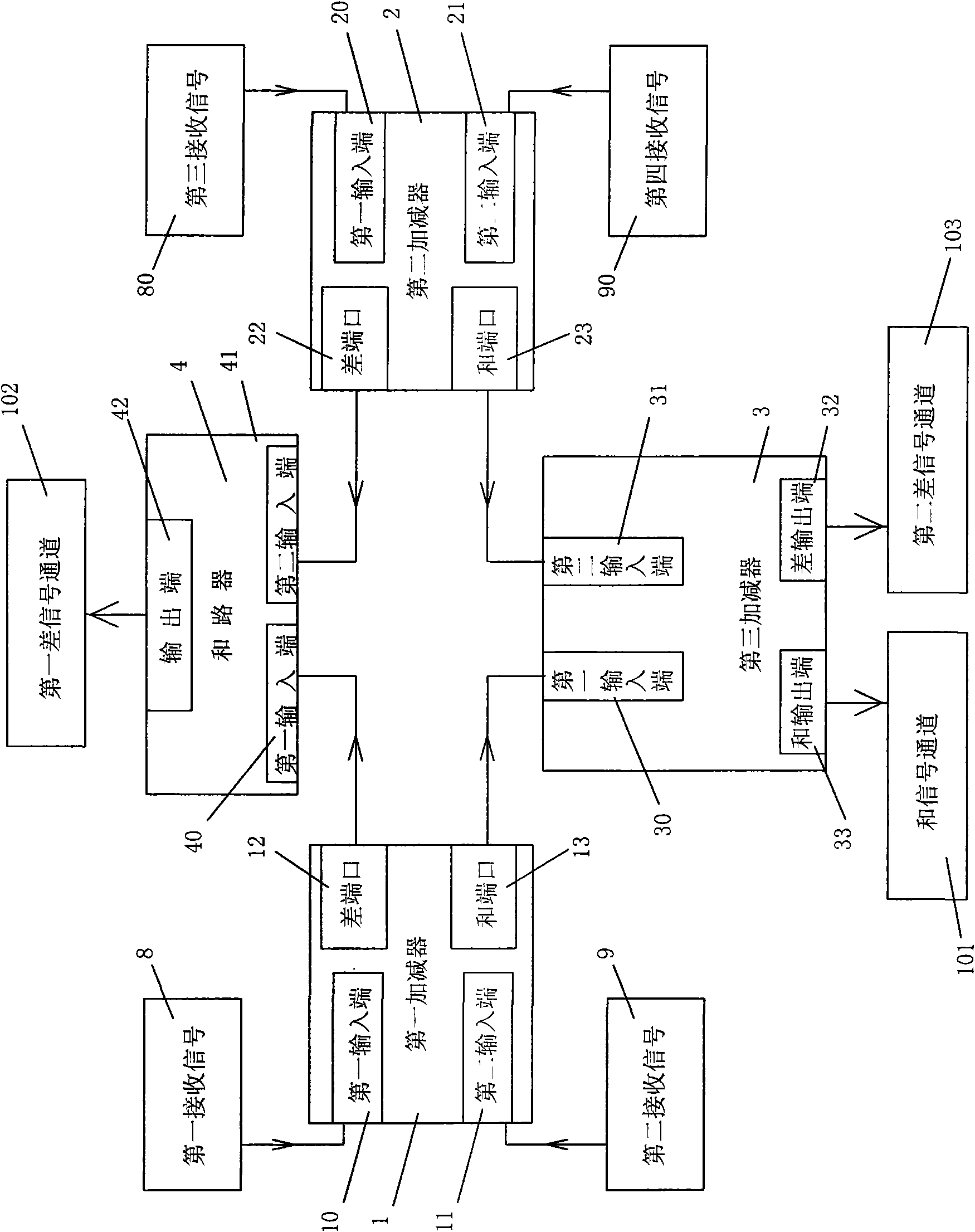
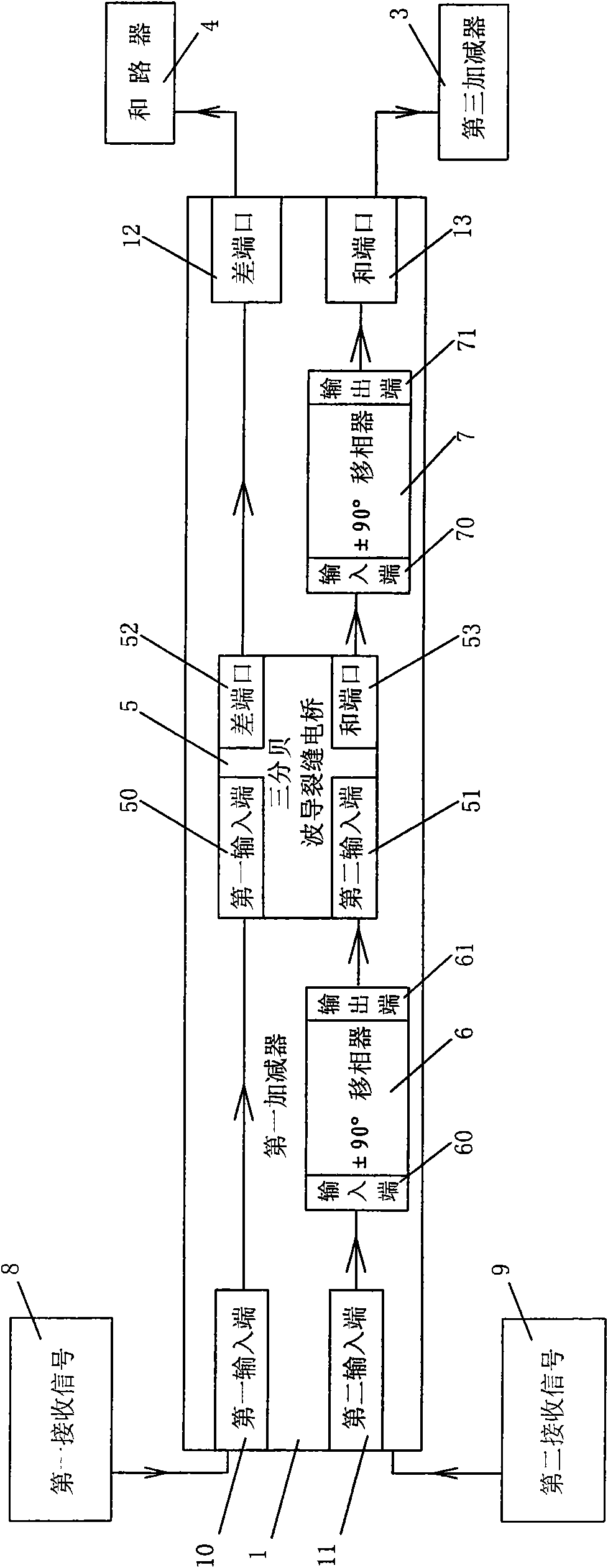
[0032] It is explained here that, in order to overcome the shortcomings in the background technology, the planar waveguide and difference network for receiving signals from various channels includes a first adder-subtractor 1 , a second adder-subtractor 2 , a third adder-subtractor 3 and a summer 4 .

[0033] like figure 2 As shown, a planar waveguide and difference network, the whole sum and difference network is a planar waveguide structure, including: a first adder-subtractor 1, a second adder-subtractor 2, a third adder-subtractor 3 and an adder-subtractor 4; The first adder-subtractor 1 described includes a first adder-subtractor first input terminal 10, a first adder-subtractor second input terminal 11, a first adder-subtractor difference port 12, a first adder-subtractor and port 13, the above-mentioned The two input terminals are respectively conne...


PUM


Abstract

The present invention discloses a planar waveguide sum-and-difference network which relates to an antenna feed network device of a single-pulse system radar system. The planar waveguide sum-and-difference network changes four receiving signals of the single-pulse antenna to a azimuth difference signal, a trim difference signal and a sum signal. The planar waveguide sum-and-difference network is composed three high-frequency waveguide adder-substracter and a combiner. The planar waveguide sum-and-difference network of the invention has the characteristics of low section, compact structure and excellent electrical property. The planar waveguide sum-and-difference network of the invention is particularly suitable for designing and manufacturing the high-efficiency single-pulse radar antenna sum-and-difference network.

Description

technical field [0001] The invention relates to a high-frequency waveguide sum-difference network, which is especially suitable for the plane-structured sum-difference network of a monopulse system antenna, and belongs to the technical field of microwave antenna feeding systems. Background technique [0002] At present, the antenna receiving device of the monopulse system is widely used in various radar and satellite communication systems. This antenna array is divided into four phases: 1, 2, 3, 4. like figure 1 As shown, it is a schematic diagram of a monopulse antenna and a sum difference network in the prior art, (1+2+3+4) is a Σ sum signal, (1+2)-(3+4) is a Δα difference signal, (1 +3)-(2+4) are Δβ difference signals, and these three signals can guide the antenna to locate and track the target with high precision. For the extraction of the sum and difference signal, the commonly used microwave device is double T (also called magic T). The same phase signal enters from...

Claims


Application Information

Patent Timeline
Patent Type & Authority Applications(China)
IPC IPC(8): H01P3/00H01P5/12
Inventor 刘洋时鹏鹏王冬
Owner BEIJING HUADA ZHIBAO ELECTRONICS SYST
Why Eureka
Try Eureka