Deep hole internal spline electrolytic machining device

A processing device and internal spline technology, which is applied in the field of deep hole internal spline electrolytic processing devices, can solve the problems of long exploration time for the number of liquid-increasing holes, complex cathode structure, and long initial feeding time, etc., and achieve shortening of auxiliary ineffective processing time, reduce the difficulty of cathode processing, and improve the effect of processing reliability

Inactive Publication Date: 2009-12-02
CHONGQING WANGJIANG IND
View PDF0 Cites 14 Cited by
  • Summary
  • Abstract
  • Description
  • Claims
  • Application Information

AI Technical Summary

Benefits of technology

This technology improves productivity while also minimizing power usage for machine tools used during cutting operations. It achieves this through two main technical means - making it easier or more efficient than traditional methods like milling.

Problems solved by technology

Technological Problem addressed in this patents relates to improving the performance and precision of electric discharge machines (EDM) such as grinding or welding processes due to their complexity and size limitations associated with traditional techniques like milling and broachting. These technical problem being solved involves finding ways to improve these machine' s capabilities while reducing costs and maintain stability over extended periods without compromising its overall effectiveness.

Method used


Image

  • Deep hole internal spline electrolytic machining device
  • Deep hole internal spline electrolytic machining device
  • Deep hole internal spline electrolytic machining device

Examples


Embodiment Construction

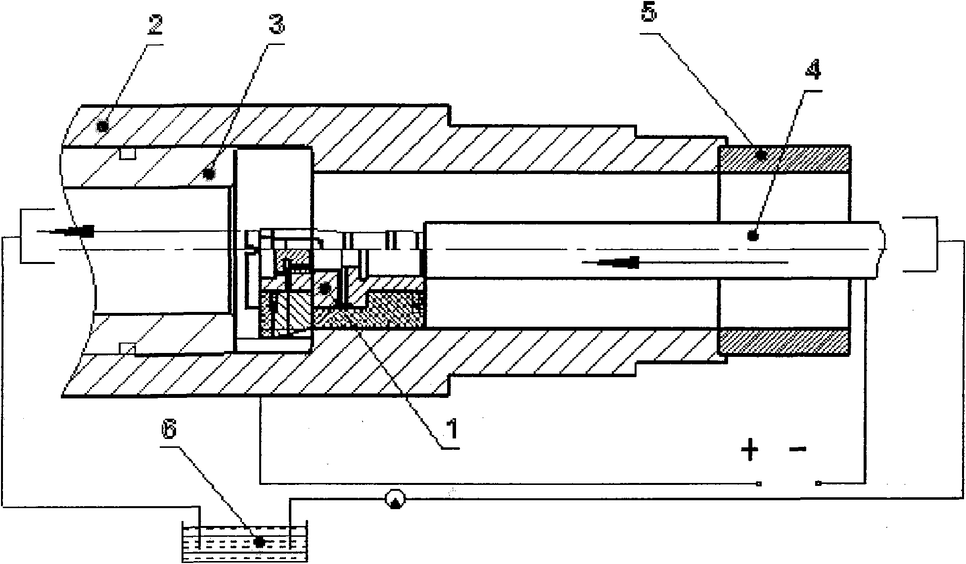
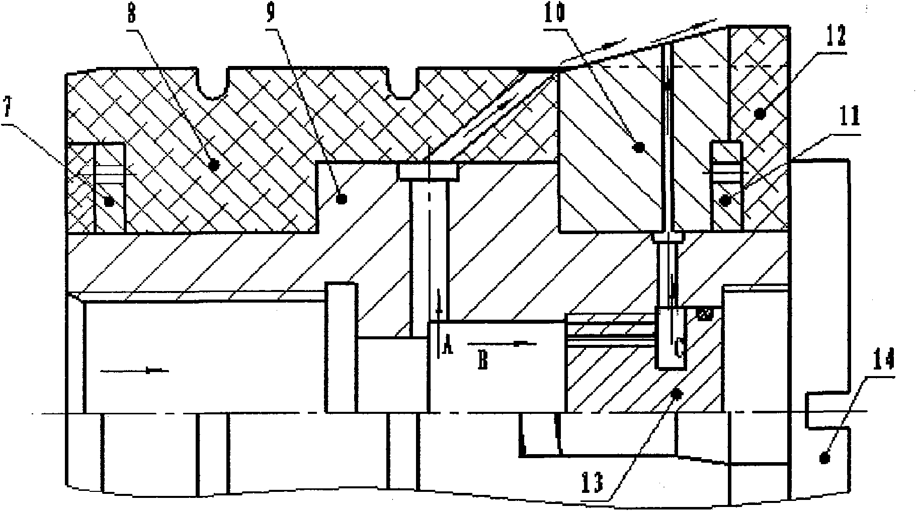
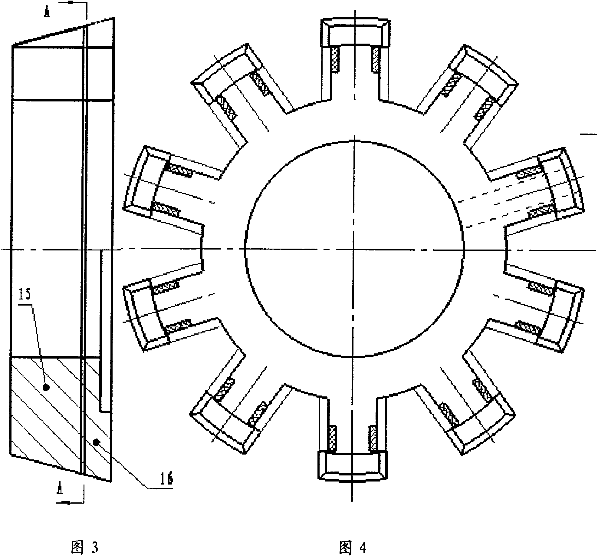
[0022] see figure 1 , figure 2 , image 3 , Figure 4 , Figure 5 , Figure 6 and Figure 7 , the spline electrolytic processing device in the deep hole of the present invention, its cathode 1 is installed in the middle part of the pre-hole of the workpiece 2 to be processed, the liquid guide auxiliary tool 3 is installed in the left part of the pre-hole of the workpiece to be processed, and the conductive liquid guide rod 4 Installed on the right part of the pre-hole of the workpiece 2 to be processed, one end of the conductive liquid guiding rod is connected to the cathode 1, and the other end passes through the process material head 5, and the process material head is connected to the right end of the processed workpiece; the liquid guiding aid 3 and the conductive The liquid guide rods 4 are communicated with the electrolyte pool 6 respectively; the positive pole of the power supply is connected with the processed workpiece 2, and the negative pole of the power suppl...


PUM


Abstract

The invention relates a deep hole internal spline electrolytic machining device, which comprises a cathode in a preformed hole of a processed workpiece, a liquid-guiding auxiliary tool, a conductive liquid-guiding rod, and an electrolytic tank communicated with the liquid-guiding auxiliary tool and the conductive liquid-guiding rod, wherein the anode of a power supply is connected with the processed workpiece, and the cathode is connected with the conductive liquid-guiding rod. The electrolytic machining device is characterized in that the cathode has a composite structure and comprises a copper body, a front guiding part, a working cone and a rear guiding part which are matched and arranged on the copper body in turn from the left to the right, and a fluid flow regulator which is arranged in the copper body and corresponds to the working cone consisting of a working front cone and a working rear cone; and the dividing part of the working front cone and the working rear cone is provided with a vertical V-shaped rectifier liquid-increasing tank. The electrolytic machining device has the advantages that: compared with three-side feeding commutation composite cathode processing, the device reduces the cathode processing difficulty, improves the processing reliability, shortens the auxiliary invalid processing time, and has shorter process stub bars, thereby reducing the production cost.

Description


Claims


Application Information

Patent Timeline
Owner CHONGQING WANGJIANG IND
Why Eureka
Try Eureka