Method and device for online monitoring and positioning turn-to-turn short circuit for rotator of water wheel generator

A technology of hydroelectric generator and inter-turn short circuit, which is applied in the direction of measuring device, using electric/magnetic device to transmit sensing components, measuring electricity, etc. Problems such as inability to dynamically detect

Active Publication Date: 2009-12-02
贵阳新光电气有限公司
View PDF0 Cites 23 Cited by
  • Summary
  • Abstract
  • Description
  • Claims
  • Application Information

AI Technical Summary

Problems solved by technology

However, due to the very low resistance of the rotor winding, it is difficult to find inter-turn short-circuit faults by method ①; affected by the accuracy of the measuring device, it is also difficult to find inter-turn short-circuit faults by method ②
Method ③ Although inter-turn short-circuit faults can be found, it can only be carried out when the power grid is out of operation or shut down for maintenance, and cannot be detected d

Method used


Image

  • Method and device for online monitoring and positioning turn-to-turn short circuit for rotator of water wheel generator
  • Method and device for online monitoring and positioning turn-to-turn short circuit for rotator of water wheel generator
  • Method and device for online monitoring and positioning turn-to-turn short circuit for rotator of water wheel generator

Examples


Embodiment 1

[0045] Example 1, such as figure 2 As shown, method one provided by the present invention is realized through the following steps:

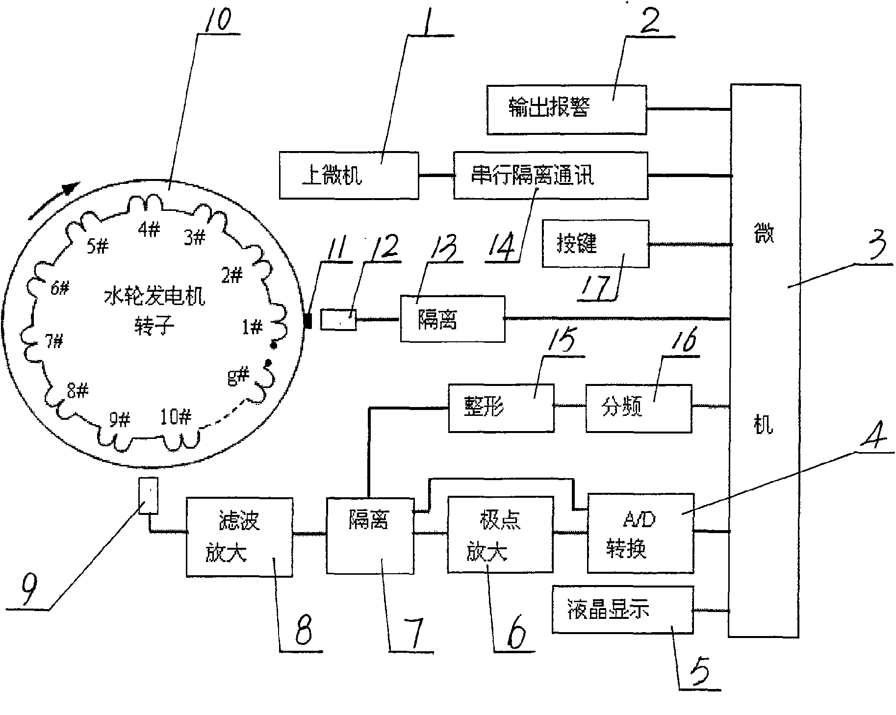
[0046] 1) Set a positioning identification mark on a certain magnetic pole of the rotor, and set the magnetic pole as 1 # magnetic poles, and number each magnetic pole in turn; the collected 1 # The magnetic pole position signal is sent to the microcomputer;

[0047] 2) The magnetic pole induction coil is installed on the inner wall of the stator or at the ventilation hole of the inner wall. The induction coil is used to obtain the induced potential waveform of each magnetic pole in one cycle of the rotor, and then filtered and amplified, and the induced potential waveform data of each magnetic pole is collected by synchronous real-time acquisition. sent to the microcomputer;

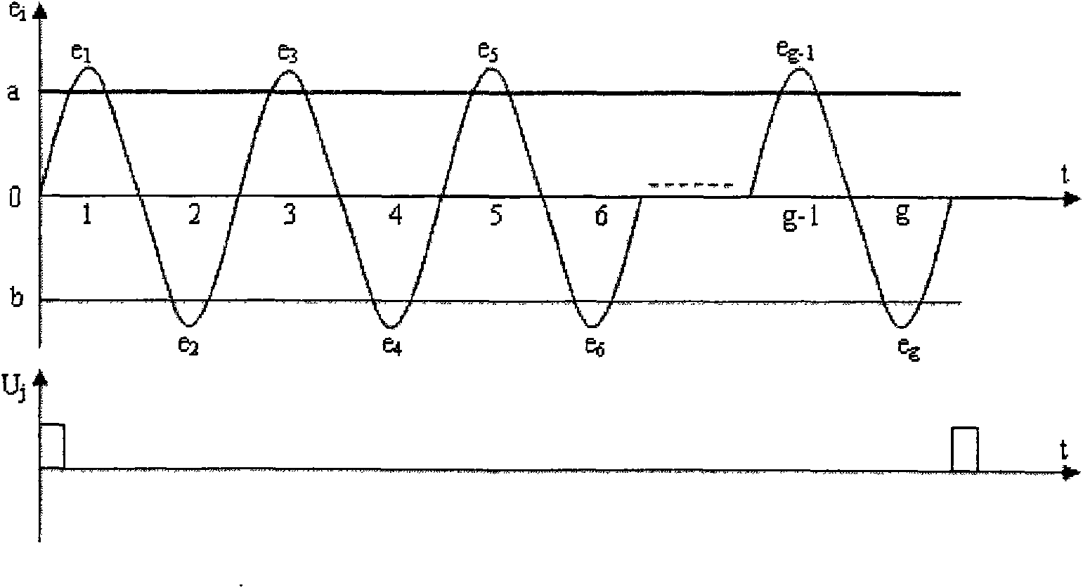
[0048] 3) The microcomputer calculates the peak value of the induced potential e of each magnetic pole within one cycle of the rotor based on the collected induced pot...

Embodiment 2

[0057] Example 2, such as image 3 As shown, method two provided by the present invention is realized through the following steps:

[0058] 1) Set a positioning identification mark on a certain magnetic pole of the rotor, and set the magnetic pole as 1 # magnetic poles, and number each magnetic pole in turn; the collected 1 # The magnetic pole position signal is sent to the microcomputer;

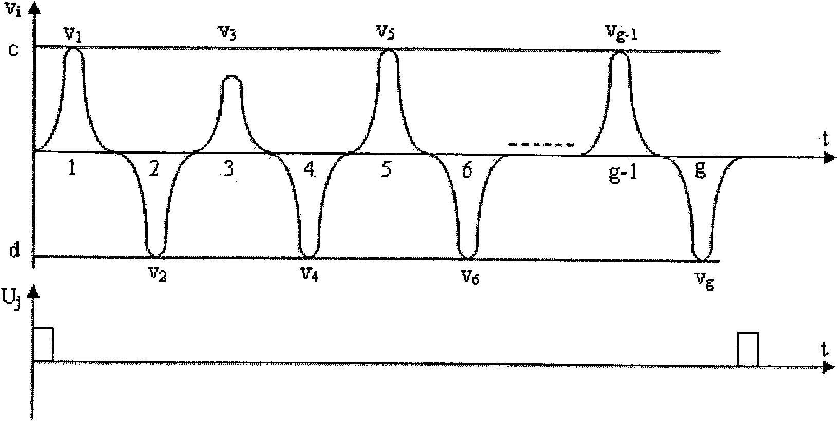
[0059] 2) The magnetic pole induction coil is installed on the inner wall of the stator or at the ventilation hole of the inner wall. The induction coil is used to obtain the induced potential waveform of each magnetic pole in one cycle of the rotor. The middle part of is automatically removed (ie figure 2 The area between ab in the middle), and the remaining peak part is amplified again to obtain the amplified waveform of the peak and pole points, and the waveform data is transmitted to the microcomputer through synchronous real-time acquisition;

[0060] 3) The microcomputer calculat...

Embodiment 3

[0068] Example 3, such as Figure 4 As shown, method three provided by the present invention is realized through the following steps:

[0069] 1) Set a positioning identification mark on a certain magnetic pole of the rotor, and set the magnetic pole as 1 # magnetic poles, and number each magnetic pole in turn; the collected 1 # The magnetic pole position signal is sent to the microcomputer;

[0070] 2) Use the induction coil to obtain the filtered and amplified waveform of the induced potential of each magnetic pole in one cycle of the rotor, or automatically remove the middle part of the approximate straight line segment in the induced potential waveform by the pole detection amplifier circuit, leaving the peak value Part of it is amplified again to obtain the peak and pole amplified waveform, and the waveform data is transmitted to the microcomputer through synchronous real-time acquisition;

[0071] 3) According to the collected induced potential waveform data or pole wav...


PUM


Abstract

The invention discloses a method and a device for online monitoring and positioning a turn-to-turn short circuit for a rotator of a water wheel generator, belongs to monitoring and protecting technology of the rotator of the water wheel generator, and aims at providing three types of methods and devices capable of carrying out online monitoring and positioning of the turn-to-turn short circuit for the rotator of the water wheel generator. The method comprises the following steps: synchronously acquiring inductive potential waveform of numbered and positioned magnetic poles through an induction coil in real time; sending the inductive potential waveform to a microcomputer and calculating an average value ep of a peak value of magnetic pole inductive potential, a pole average value vp; and comparing the smallest peak value e min of the inductive potential and the smallest pole value v min of the inductive potential with the ep and vp and making the judgment. The device comprises a positioning identification label (11), first and second separated circuits (13, 7), the microcomputer (3), a position sensor (12), a filtering amplifying circuit (8), an A/D transferring circuit (4), a magnetic pole induction coil (9), a frequency dividing circuit (15), a wave-shaping circuit (16) and a display (5), and a device is additionally provided with two pole amplifying circuit (6) on the basis of the devices.

Description

Technical field: [0001] The invention relates to three methods for on-line monitoring and positioning of inter-turn short-circuits of generator rotors, in particular to three methods for on-line monitoring and positioning of inter-turn short-circuits of hydraulic generator rotors; the invention also relates to devices respectively implementing the above methods. Background technique: [0002] In current generator rotor turn-to-turn short-circuit technology, there are many studies on turbogenerators, but few studies on hydroelectric generators. Since the turbogenerator is a hidden pole type, there are only two magnetic poles, and the inter-turn short circuit is reflected in the slot of the rotor; while the hydroelectric generator is a salient pole type, there are many magnetic poles, and the inter-turn short circuit is reflected in the rotor slot. within the magnetic pole. The number of turns in the rotor slot of the steam turbine generator is relatively small, generally onl...

Claims


Application Information

Patent Timeline
IPC IPC(8): G01R31/06G01D5/12H02K1/22
Inventor 曾广
Owner 贵阳新光电气有限公司
Why Eureka
Try Eureka