Electric motor

A technology of motors and windings, applied in the field of motors, can solve problems such as motor output limitations, and achieve the effect of preventing temperature rise and preventing switching actions from being limited

Inactive Publication Date: 2009-12-02
NIDEC SHIBAURA CORP
View PDF5 Cites 5 Cited by
  • Summary
  • Abstract
  • Description
  • Claims
  • Application Information

AI Technical Summary

Problems solved by technology

Therefore, in order to maintain the above-mentioned switching element at an appropriate operating temperature, it is necessary to limit the switching operation of the switching element, but in this case, the output of the motor is also limited.

Method used


Image

  • Electric motor
  • Electric motor
  • Electric motor

Examples


Embodiment approach 1

[0058] -the whole frame-

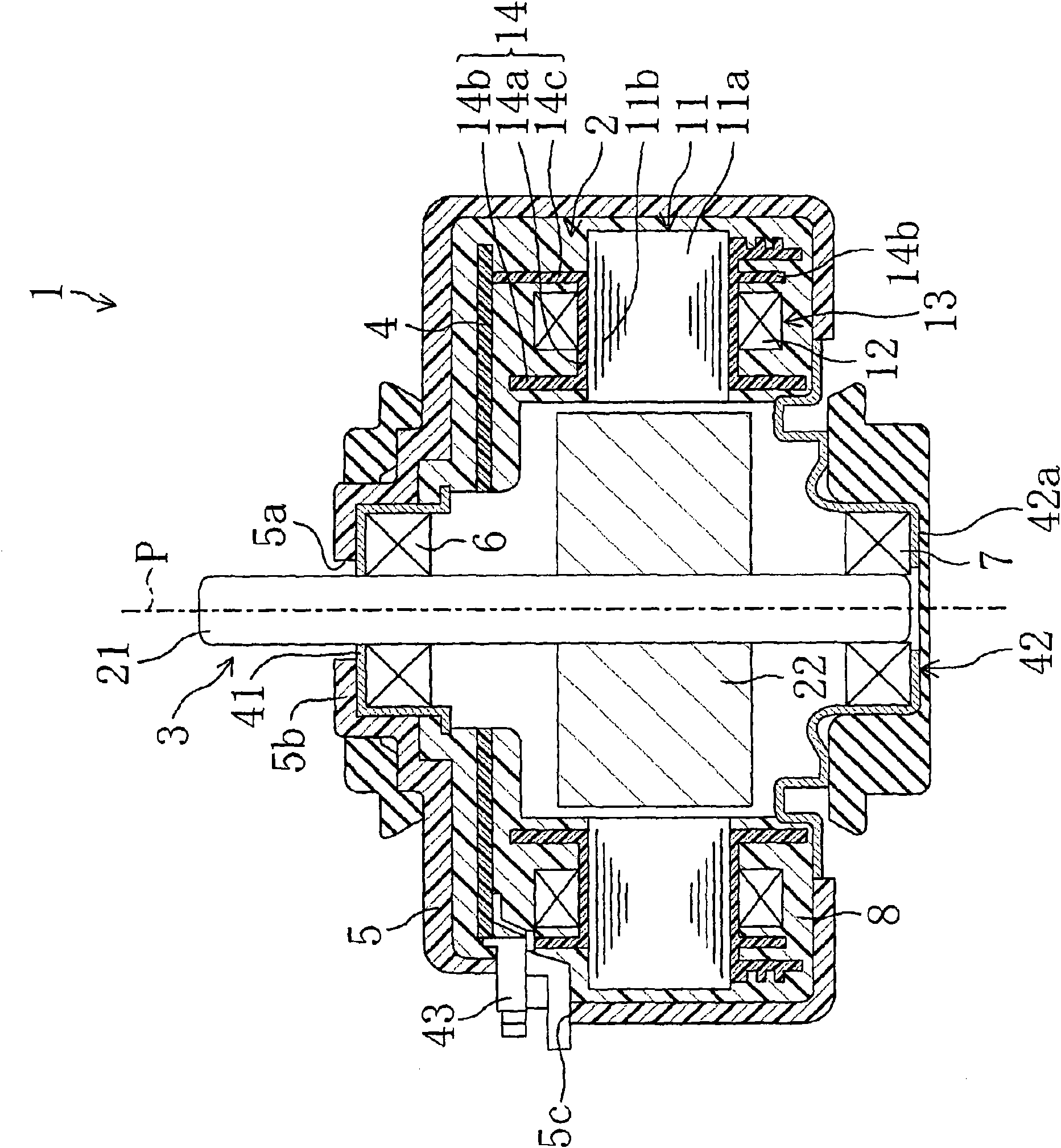
[0059] Embodiment 1 of the present invention will be described below. Such as figure 1 as well as figure 2 As shown, the motor 1 of this embodiment is a so-called brushless DC motor in which the rotor 3 is rotationally driven relative to the stator 2 by supplying electric power to the winding 13 of the stator 2 at predetermined timing by the control circuit 30 . Specifically, the electric motor 1 includes: a substantially cylindrical stator 2 in which a plurality of windings 13, 13, . rotor 3; a substrate 4 having a control circuit 30 for controlling the energization of the plurality of windings 13, 13, ... of the stator 2; shell5. That is, the motor 1 is configured to form a rotating magnetic field in the stator 2 by controlling the energization of the plurality of windings 13, 13, . . . Perform rotary drive.

[0060] The stator 2 includes: a stator core 11 formed by laminating a plurality of steel plates; and a plurality of coils 12 , 12 , ....

Embodiment approach 2

[0092] Below, according to Figure 7 as well as Figure 8 A motor according to Embodiment 2 will be described. The motor according to the second embodiment differs from the first embodiment only in the structure of the semiconductor chip, so the same reference numerals are assigned to the same structures, and only the different parts will be described below.

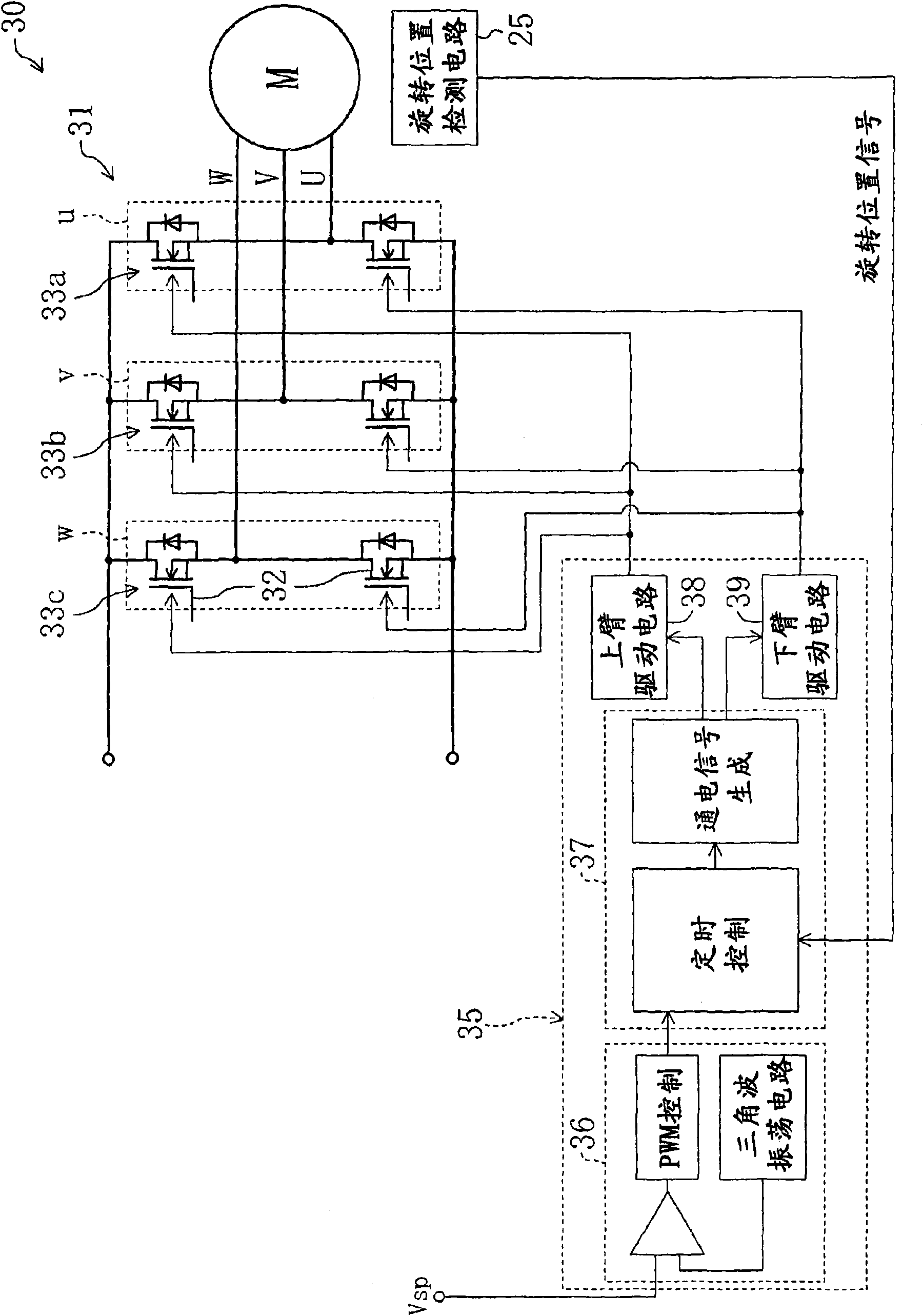
[0093] Specifically, as Figure 7 As shown, the six switching elements 32 constituting the switching circuit 51 of the control circuit are composed of semiconductor chips uH, uL, vH, vL, wH, and wL, respectively. That is, compared to the number of semiconductor chips in the first embodiment described above, which is three, this embodiment is different in that the number of semiconductor chips described above is six.

[0094] Figure 8 Show six semiconductor chips uH, uL, vH, vL, wH, wL on the substrate 4 (in Figure 8 Indicated by the dotted line) on the configuration. as it should Figure 8 As shown, even in the ...


PUM


Abstract

The invention provides an electric motor. On outside in axial cord direction of a stator that formed by windings with a plurality of phases annularly around the axial cord, in the way that extends in the axial cord intersecting direction, in the electric motor provided with cardinal plate having a semiconductor chip with a switching element, on-off action of the switching element will not be restricted because of heat generated in the windings of the stator. A semiconductor chip (u, v, w) having a switching element (32) is arranged on the cardinal plate (4) to make at least part of the windings (13) have no phases with electricity following on-off action of the switching element (32) and at least one overlap of the gaps between the windings (13) and the neighboring windings (13).

Description

technical field [0001] The present invention relates to a motor that controls energization to coils of a plurality of phases by using a switching element, and particularly relates to the technical field of temperature countermeasures for the switching element. Background technique [0002] Conventionally, electric motors have been used as drive sources for various devices. A motor having a general structure includes: a substantially cylindrical stator having windings of a plurality of phases; rotor. In such a motor, the windings of the plurality of phases of the stator are sequentially energized by the switching operation of the switching elements to form a rotating magnetic field in the stator, thereby rotationally driving the rotor including the magnets. [0003] In addition, in the motor having the above-mentioned structure, as described in Patent Document 1, for example, a substantially cylindrical stator having the above-mentioned switching element is arranged outside...

Claims


Application Information

Patent Timeline
Patent Type & Authority Applications(China)
IPC IPC(8): H02K3/00
Inventor 加藤健一
Owner NIDEC SHIBAURA CORP
Why Eureka
Try Eureka