Printing equipment

A technology for printing equipment and fixed frames, applied in printing, printing machines, rotary printing machines, etc., can solve problems such as paper jams and inconsistent rotation of two printing rollers, affecting printing quality, etc., to achieve faster drying speed, simple structure, and easy operation convenient effect

Inactive Publication Date: 2018-08-17
重庆川之舟印务设计有限公司
View PDF0 Cites 2 Cited by
  • Summary
  • Abstract
  • Description
  • Claims
  • Application Information

AI Technical Summary

Problems solved by technology

[0004] The present invention intends to provide a printing equipment to solve the problem that traditional double-sided printing equipment requires two printing rollers to drive the cardboard forward, which may easily cause paper jams and inconsistent rotation of the two printing rollers, which will affect the printing quality.

Method used


Image

  • Printing equipment
  • Printing equipment
  • Printing equipment

Examples


Embodiment Construction

[0021] The following is further described in detail through specific implementation methods:

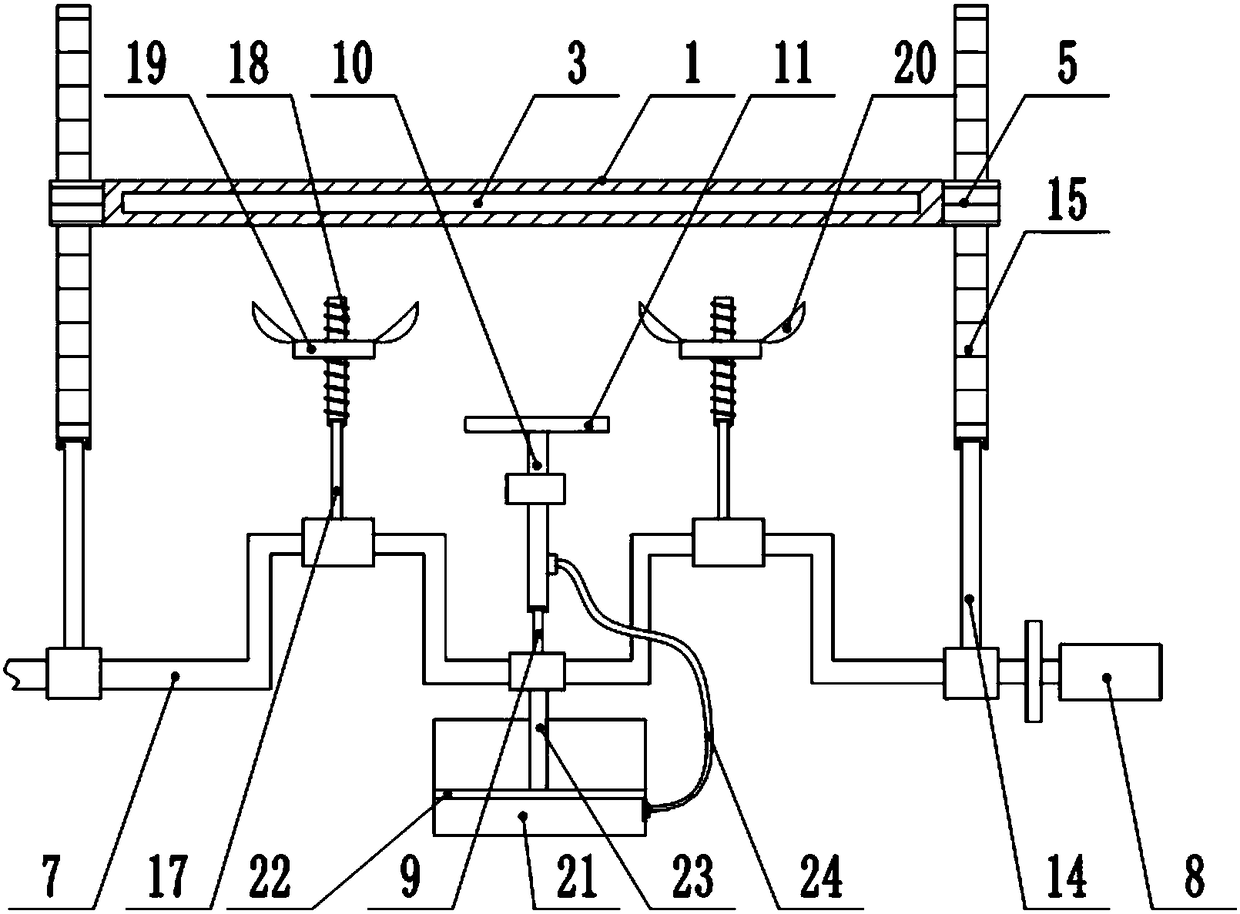
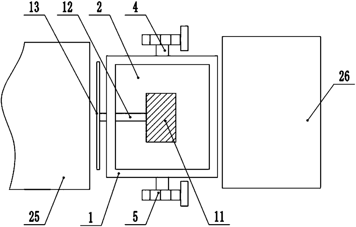
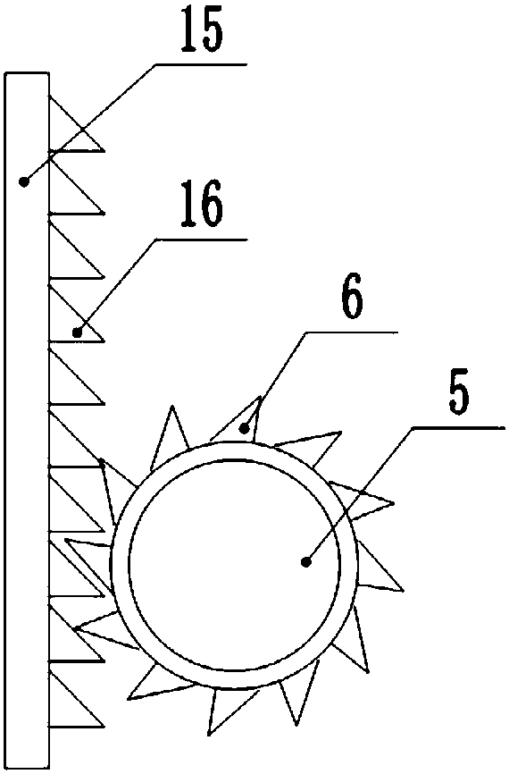
[0022] The reference signs in the drawings of the description include: fixed frame 1, through slot 2, through hole 3, transverse shaft 4, gear 5, one-way tooth 6, crankshaft 7, drive motor 8, first connecting rod 9, printing tube 10 , printing plate 11, cross bar 12, cutting knife 13, push rod 14, rack 15, tooth 16, second connecting rod 17, screw mandrel 18, nut 19, rotating blade 20, ink tank 21, piston 22, piston Rod 23 , conduit 24 , conveyor belt 25 , collection box 26 .

[0023] The embodiment is basically as attached figure 1 Shown: a printing device, including a frame and an overturning mechanism, the overturning mechanism includes a fixed frame 1, combined with figure 2 As shown, the fixed frame 1 is provided with a through groove 2, and the side wall of the fixed frame 1 is provided with a through hole 3, the top of the through hole 3 is provided with a first magnet, and...


PUM


Abstract

The invention relates to the field of printing devices, and discloses printing equipment. The printing equipment comprises a machine frame and a fixing frame, wherein a through groove which penetratesthrough the fixing frame is formed in the fixing frame, and a through hole is formed in the side wall of the fixing frame; cross shafts are fixedly connected to the two ends of the fixing frame, thecross shafts are coaxially and fixedly connected with gears, and a crankshaft is arranged below the fixing frame; a main journal of the crankshaft is rotationally connected with a first connecting rod, the other end of the first connecting rod is rotationally connected with a printing tube, the printing tube is slidably connected to the machine frame, and the top of the printing tube is connectedwith a printing plate; the printing tube is further connected with a cutting knife, push rods are rotationally arranged on the portions, on the two sides of the printing tube, of the main journal correspondingly, the other ends of the push rods are rotationally connected with racks, the racks are slidably connected to the machine frame, and the racks can be meshed with the gears, and second connecting rods are rotationally connected to the portions, at the two ends of the printing tube, of the main journal; the other ends of the second connecting rods are rotationally connected with screw rods, the screw rods are in threaded connection with nuts, and the top ends of the nuts are hinged to rotating blades. According to the device, automatically turning over a paper board during printing isrealized.

Description

technical field [0001] The invention relates to the field of printing devices, in particular to a printing device. Background technique [0002] Printing (Printing, Graphic Art) is to transfer the ink to the surface of paper, fabrics, plastics, leather and other materials through the process of plate making, ink application, and pressure to copy the original content in batches. Technology. Printing is the process of transferring the approved printing plate to the substrate through printing machinery and special ink. According to the relative positions of graphic and non-graphical areas on the printing plate, common printing methods can be divided into four categories: letterpress printing, gravure printing, lithographic printing and stencil printing. [0003] Traditional printing devices usually print on one side, which cannot meet the needs of double-sided printing for some cardboards. Therefore, in order to meet the needs, double-sided printing devices are currently wide...

Claims


Application Information

Patent Timeline
Patent Type & Authority Applications(China)
IPC IPC(8): B41F17/00B41F23/04B26D7/27
CPCB41F17/00B26D7/27B41F23/0443
Inventor 杨学智
Owner 重庆川之舟印务设计有限公司
Why Eureka
Try Eureka