Medical image processing device and medical image processing method

An image processing device and medical technology, which is applied in the field of medical image processing, can solve problems such as low reliability and reduced detection efficiency of bulge shape

Active Publication Date: 2011-08-24
OLYMPUS CORP
View PDF2 Cites 0 Cited by
  • Summary
  • Abstract
  • Description
  • Claims
  • Application Information

AI Technical Summary

Problems solved by technology

[0006] When the image processing method of Japanese Patent Application Laid-Open No. 2005-192880 is used as processing for estimating a three-dimensional model from a two-dimensional image acquired by an endoscope, it is reliable due to the Estimation is performed on 3D data with low reliability, so there is a problem that the detection efficiency of raised shapes decreases:

Method used


Image

  • Medical image processing device and medical image processing method
  • Medical image processing device and medical image processing method
  • Medical image processing device and medical image processing method

Examples


no. 1 approach

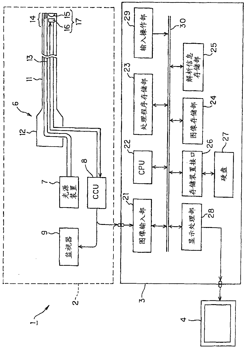
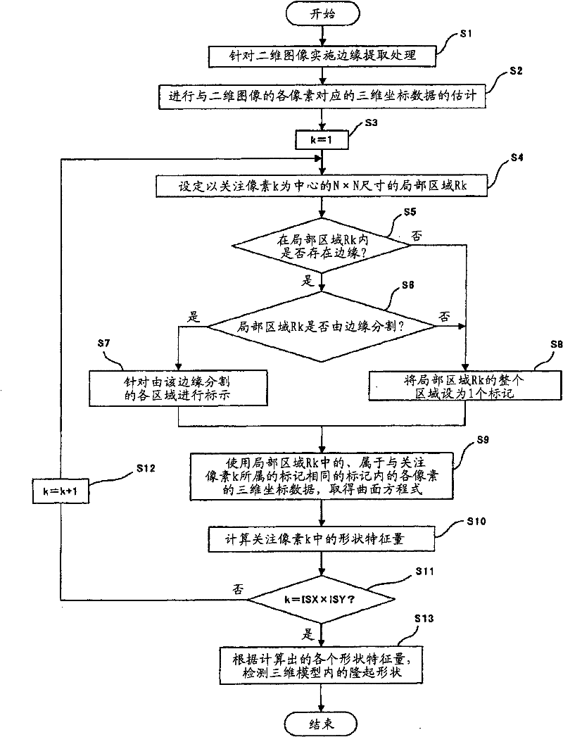
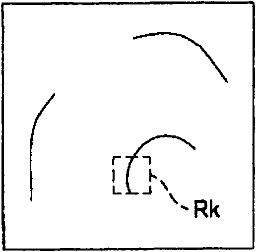
[0030] Figure 1 to Figure 6 It relates to the first embodiment of the present invention. figure 1 It is a diagram showing an example of the overall configuration of an endoscope system to which the medical image processing device according to the embodiment of the present invention is applied. figure 2 yes means figure 1 A flowchart of an example of a processing procedure executed by the medical image processing apparatus in the first embodiment. image 3 is to pass figure 1 An example of an edge image acquired by the medical image processing device. Figure 4 yes image 3 A zoom-in view of a local region in the edge image. Figure 5 is for Figure 4 A schematic diagram of the state when a local area is marked. Figure 6 is that if Figure 5 It is a diagram showing the correspondence relationship between each marked region and a portion of the three-dimensional model in which the three-dimensional coordinate data of each region is stored.

[0031] Such as figure 1 ...

no. 2 approach

[0068] Figure 7 and Figure 8 It relates to the second embodiment of the present invention. Figure 7 yes means figure 1 A flowchart of an example of a processing procedure performed by the medical image processing apparatus in the second embodiment. Figure 8 yes means figure 1 The processing steps performed by the medical image processing device in the second embodiment and with Figure 7 Flowcharts of different examples.

[0069] In addition, detailed description of parts having the same configuration as that of the first embodiment will be omitted. In addition, the configuration of the endoscope system 1 used in this embodiment is the same as that of the first embodiment.

[0070] Next, image processing operations performed in the medical image processing apparatus 3 will be described.

[0071] Based on the two-dimensional image output from the image input unit 21, the CPU 22 performs processing such as geometrical conversion based on brightness information of the ...

no. 3 approach

[0102] Figure 9 It relates to the third embodiment of the present invention. Figure 9 yes means figure 1 A flowchart of an example of a processing procedure performed by the medical image processing apparatus in the third embodiment.

[0103] In addition, detailed description of parts having the same configuration as those of the first embodiment and the second embodiment will be omitted. In addition, the structure of the endoscope system 1 used for this embodiment is the same as that of 1st Embodiment and 2nd Embodiment.

[0104] Next, image processing operations performed in the medical image processing apparatus 3 will be described.

[0105] First, the CPU 22 implements the two-dimensional image already described in the description of the first embodiment, and figure 2 The same edge extraction process as in step S1, and mark each edge extracted ( Figure 9 Steps S301 and S302).

[0106] In addition, in this embodiment, the CPU 22 performs Figure 9 In the processi...


PUM


Abstract

A medical image processing device is characterized in comprising an edge extracting unit for extracting a two-dimensional image of a biomedical tissue input from a medical image picking-up device; a three-dimensional model estimating unit for estimating a three-dimensional image of the biomedical tissue; a local region setting unit for setting a local region where a pixel of interest is treated as the center in the two-dimensional image; a judging unit for judging whether or not the local region is divided by at least a part of the edge extracted in the extracting unit; a shape characteristiccalculating unit for calculating a shape characteristic amount of the pixel of interest while using three-dimensional data of regions that are not divided by the edge in the edge extracting unit out of the local region based on a judging result of the judging unit and that correspond to a region where the pixel of interest exists; and a projecting shape detecting unit for detecting a projecting shape based on a calculation result of the shape characteristic amount calculating unit.

Description

technical field [0001] The present invention relates to a medical image processing device and a medical image processing method, and more particularly to a medical image processing device and a medical image processing method for estimating a three-dimensional model of a living tissue from a two-dimensional image of the living tissue. Background technique [0002] Conventionally, in the medical field, observation using imaging equipment such as X-ray diagnostic equipment, CT, MRI, ultrasonic observation equipment, and endoscope equipment has been widely performed. The endoscope device in this kind of image pickup equipment has the following functions and structures, for example: it has an insertion portion that can be inserted into a body cavity, and the objective optical system configured at the front end of the insertion portion is photographed by an imaging unit such as a solid-state imaging device. The captured image inside the body cavity is output as an imaging signal,...

Claims


Application Information

Patent Timeline
Patent Type & Authority Patents(China)
IPC IPC(8): A61B1/04A61B6/00A61B6/03G02B23/24G06T1/00
CPCG06T2207/10068A61B6/5211G06T7/0083G06T2207/30028G06T7/0053A61B1/04G06T7/507G06T7/12
Inventor 井上凉子
Owner OLYMPUS CORP
Why Eureka
Try Eureka