
Machine tool having brushless motor

A brushless motor and power tool technology, applied in the direction of manufacturing tools, striking tools, electric components, etc., can solve the problems of shortening the overall length, dead zone of the cover, etc., to reduce slack, shorten the lead, and reduce the occlusion of the lead. Effect

Inactive Publication Date: 2009-12-02
MAX CO LTD
View PDF3 Cites 15 Cited by
  • Summary
  • Abstract
  • Description
  • Claims
  • Application Information

AI Technical Summary

Problems solved by technology

On the other hand, when the motor shaft and the output shaft are arranged in a state of staggering up and down in two steps, the output shaft is higher than the motor shaft. In addition, if a brushless motor is used, the overall length becomes shorter, and a dead zone is generated in the case.

Method used


Image

  • Machine tool having brushless motor
  • Machine tool having brushless motor
  • Machine tool having brushless motor

Examples


Embodiment Construction

[0034] Hereinafter, embodiments of the present invention will be described with reference to the drawings.

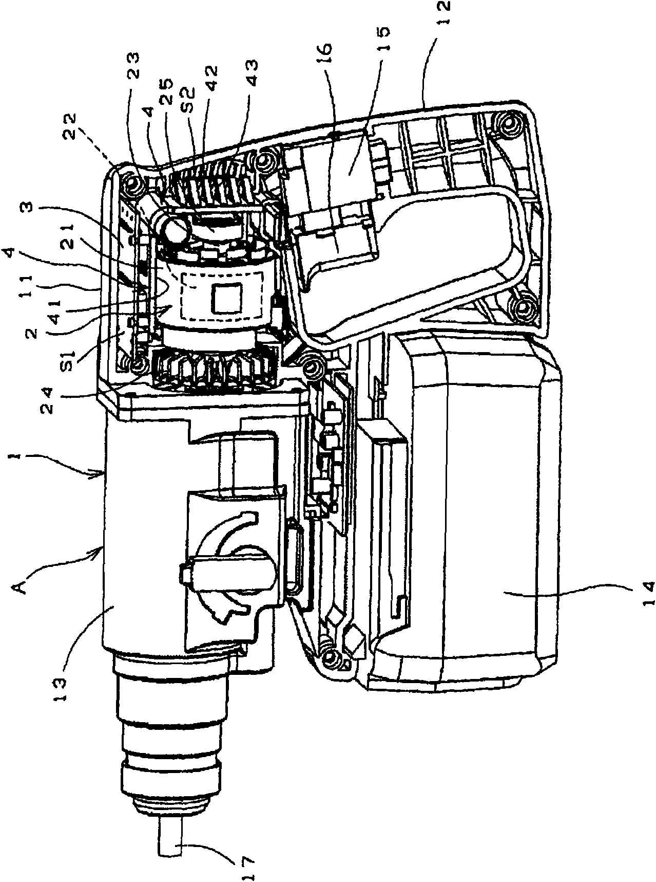
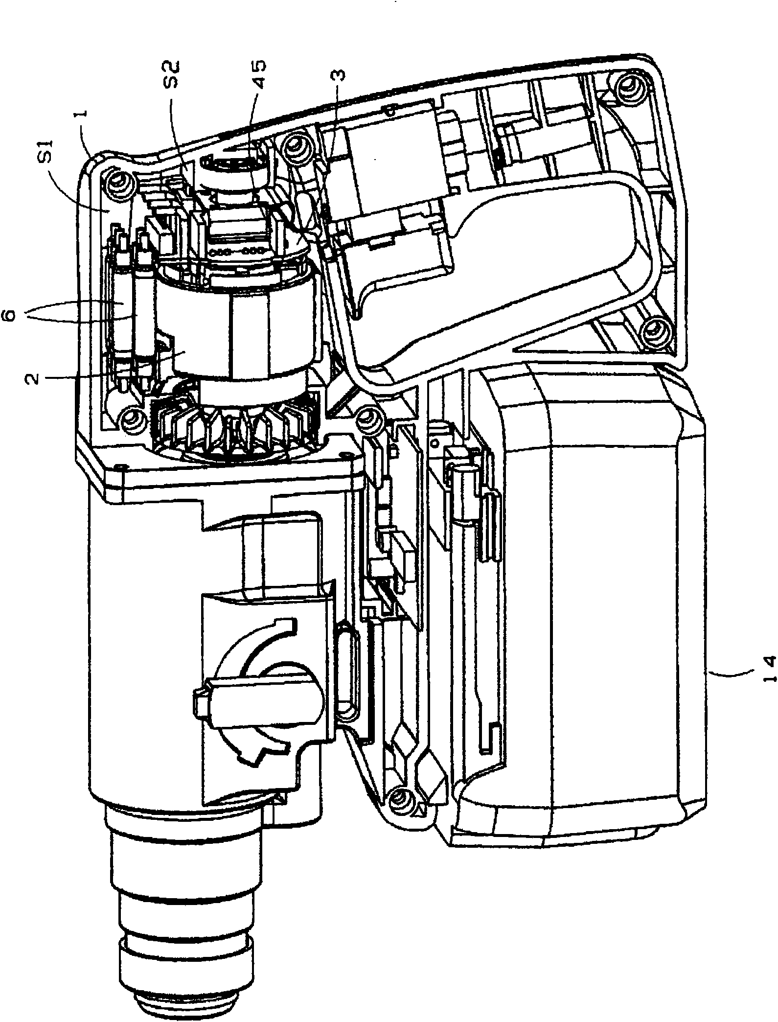
[0035] Figure 6 , 7 FIG. 3 shows a hammer drill A incorporating a brushless motor 2 as an electric tool according to an embodiment of the present invention. The housing 1 of the electric hammer drill A is composed of a motor housing part 11, a handle 12 integrally formed with the housing part 11, and a housing housing part 13 for accommodating the rotary driving part connected to the front part of the motor housing part 11, etc. , In addition, a DC battery power supply box 14 for supplying DC power is provided at the lower part of the casing 1 .

[0036] A brushless motor 2 is built in the motor housing part 11, and a trigger 16 that can be operated by holding the handle part 12 with a hand is provided on the handle 12, and the above-mentioned brushless motor 2 is started by pressing the trigger 16. Switch 15 action.

[0037] The brushless motor 2 has a stator 21, ...


PUM


Abstract

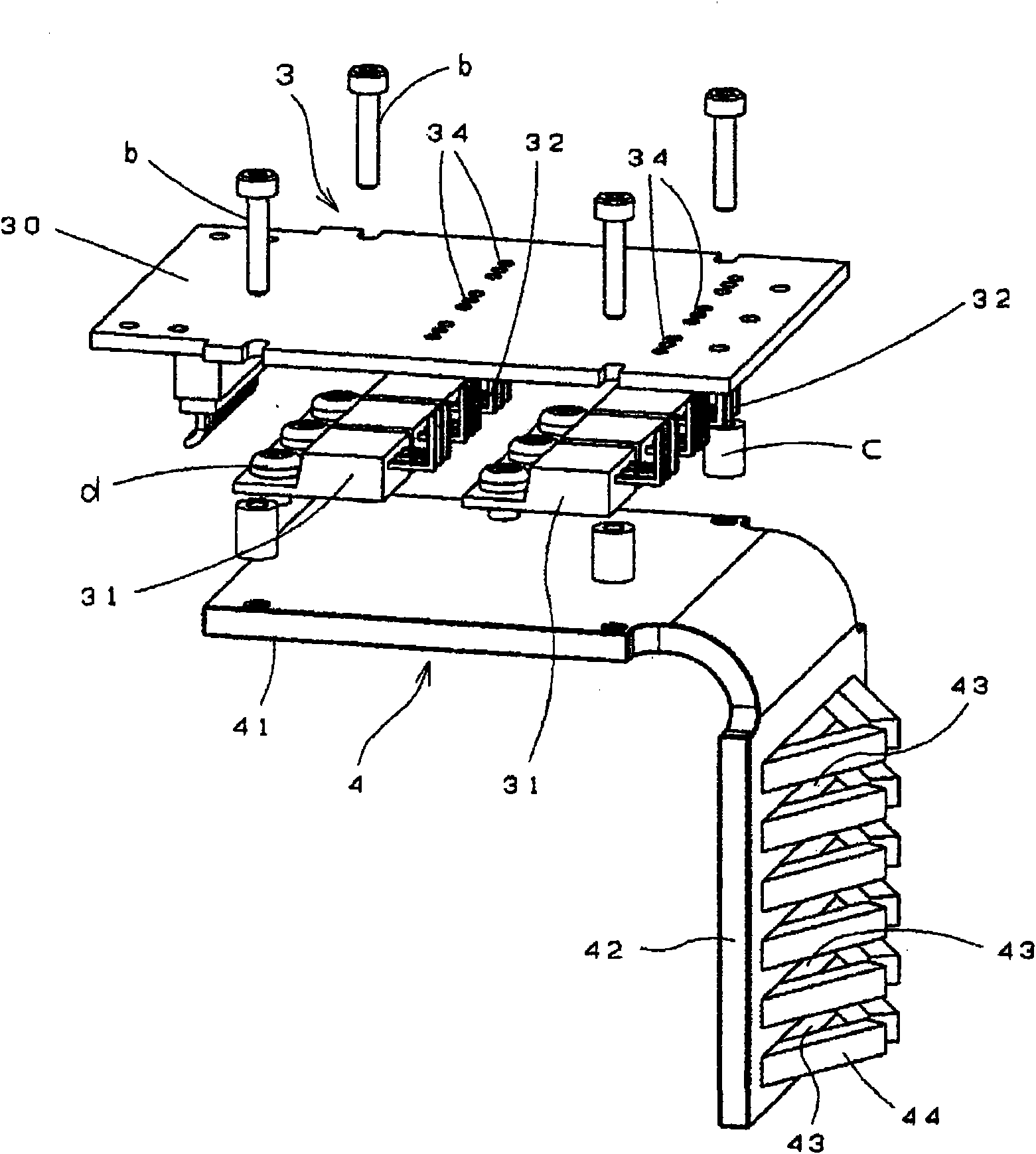
Disclosed is a machine tool wherein a power substrate (3) having an electronic component for controlling revolution of a brushless motor is arranged in a first space (S1) above the brushless motor and a heat sink for cooling the power substrate (3) is arranged in a second space (S2) in the back of the brushless motor.

Description

technical field [0001] The present invention relates to an electric power tool equipped with a brushless motor, and more particularly to an electric power tool that efficiently utilizes the features of the structure of the electric power tool on which the brushless motor is mounted. Background technique [0002] Motors used as electric tools often use motors driven by DC power sources, and one type of such motors is a brushless motor that does not use brushes or commutators. The brushless motor does not use brushes and commutators, but includes a power board and a control board for rotation control of the brushless motor, and FETs, which are electronic components for motor rotation control, are mounted on the power board. [0003] However, the electronic components for rotation control tend to generate heat due to the driving of the motor, and the continuation of the driving will cause the electronic components to overheat and be damaged, causing malfunctions such as malfunc...

Claims


Application Information

Patent Timeline
Patent Type & Authority Applications(China)
IPC IPC(8): B25F5/00
CPCH02K11/0073B25D16/00B25F5/008H02K7/145H02K11/33
Inventor 坂卷一弥寺西明加藤浩二荒井健一
Owner MAX CO LTD
Learn More