Method for building dynamic model of electrocardio signal RR interval and QT interval and applications thereof

A kinetic model, ECG signal technology, applied in applications, medical science, sensors, etc., can solve problems such as staying, not establishing mathematical kinetic models, etc.

Inactive Publication Date: 2009-12-09
江依法
View PDF0 Cites 8 Cited by
  • Summary
  • Abstract
  • Description
  • Claims
  • Application Information

AI Technical Summary

Problems solved by technology

[0012] Although there is an obvious causal relationship between RRI and QTI, research so far has remained ...

Method used


Image

  • Method for building dynamic model of electrocardio signal RR interval and QT interval and applications thereof
  • Method for building dynamic model of electrocardio signal RR interval and QT interval and applications thereof
  • Method for building dynamic model of electrocardio signal RR interval and QT interval and applications thereof

Examples


Embodiment 1

[0054] Embodiment 1 The establishment of the kinetic model from RRI to QTI

[0055] Taking RRI as the input signal and QTI as the output signal, the following dynamic model can be established between the RRI and QTI signals.

[0056]

[0057] The transfer function H(s) of this model is a second-order linear model, because the difference in phase and amplitude between the QTI signal and the RRI signal can be approximated by such a mathematical model. ω in H(s) n is the natural frequency of the system, take the main frequency of the RRI signal, that is, the angular frequency of the LF component in HRV is ω n value. that is

[0058] ω n =2πf LF ,.............................................(1)

[0059] f LF is the angular frequency of the LF component in HRV, which is about 0.1 Hz. The gain of the transfer function H(s) is:

[0060] | G ( jω ) | = k ...

Embodiment 2

[0068] Embodiment 2 The establishment of the kinetic model from RRI to QTI

[0069] Taking RRI as the input signal and QTI as the output signal, the following dynamic model can be established between the RRI and QTI signals.

[0070]

[0071] Input the actual RRI signal into H(s) so that the output signal generated by the simulation is consistent with the QTI s The sum of squared errors between the measured QTIs is the smallest, which can be obtained

[0072] e(D)=∑[QTI s (t)-QTI(t)] 2

[0073] e(K)=∑[QTI s (t)-QTI(t)] 2

[0074] The D value and K value when the e(D) and e(K) values ​​are minimum are the D value and K value of the system.

Embodiment 3

[0075] Example 3 Method for Obtaining Unit Step Response Function

[0076] 1. Recruitment of subjects

[0077] The present invention recruited 8 healthy adults to participate in the experiment (no heart disease before, ECG examination without premature beats, etc.), including 4 males and 4 females, with an average age of 26.2±7.8 years old.

[0078] 2. ECG inspection and automatic identification of R and T waves

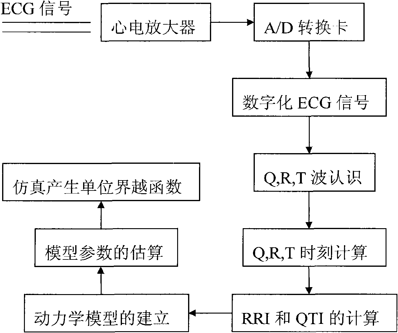
[0079] Such as figure 1 As shown, the chest leads V2 and V3 obtain signals, amplify, filter, and A / D convert to obtain digitized ECG signals, and input them into a computer for signal processing. After the ECG signal is saved to a file, the offline R and T waves are automatically identified, and the apex positions of the R and Q waves are calculated. Waveform identification adopts pattern matching technology (Pattern matching), and QT interval is defined as the time interval from the beginning of Q wave to the end of T wave. All the equipment was tested after rep...


PUM

PropertyMeasurementUnit
Sampling frequencyaaaaaaaaaa

Abstract

The invention relates to a method for building a dynamic model of electrocardio signal RR interval and QT interval and applications thereof. The method for building the dynamic model of electrocardio signal RR interval and QT interval utilizes RRI as an input signal and QTI as an output signal to build a linear relation dynamic model between RRI signal and QTI signal, preferably a second order linear relation dynamic model. Based on the high correlation between RRI and QTI and the fact that QTI lags behind RRI, a linear model is built between RRI and QTI; according to the data of clients detected in experiments, systematic parameter estimation is carried out on a transfer function to obtain a special transfer function. And then, the system is simulated, QTI obtained from simulation is found to be very close to the actually measured QTI. The transfer characteristic between RRI and QTI reflects the functional state of hearts, and the heart function can correspondingly be evaluated by using the unit step of the transfer function, thus the system can have a certain clinical research prospect.

Description

technical field [0001] The invention relates to a method for establishing a dynamic model of the electrocardiographic signal RR interval and QT interval and the application of the model. Background technique [0002] Discrete RR interval (R-R interval, RRI) signal and QT interval (Q-T interval, QTI) signal can be obtained by continuously measuring Q wave, R wave and T wave of electrocardiology (ECG). The RRI signal represents the change of heart rhythm, that is, heart rate variability (HRV), while the QTI signal represents the change of ventricular muscle action potential duration (action potential duration, APD). QTI signals are affected by various physiological and pathological factors, such as heart rhythm, autonomic nervous tension, hormone levels, drugs, electrolytes and heart function, etc., and the influence of heart rhythm is particularly important. [0003] In 1920, Bazett was the first to recognize the influence of heart rhythm changes on QTI, and proposed the fam...

Claims


Application Information

Patent Timeline
IPC IPC(8): A61B5/02A61B5/0402
Inventor 江依法
Owner 江依法
Why Eureka
Try Eureka