Explosion-proof safety tyre of vehicle

一种安全轮胎、车辆的技术,应用在轮胎测量、车辆部件、轮胎零部件等方向,能够解决车辆行使方向失控、车辆安全隐患、车辆行驶方向失控等问题,达到方便装卸过程、保证基本性能、杜绝安全隐患的效果

Active Publication Date: 2009-12-09
吴小寅 +1
View PDF0 Cites 15 Cited by
  • Summary
  • Abstract
  • Description
  • Claims
  • Application Information

AI Technical Summary

Problems solved by technology

However, at the moment of piercing or rupture, it is easy to cause the vehicle's driving direction to suddenly lose control and deviate, thus causing traffic accidents, especially in the process of high-speed driving, the consequences are particularly serious
Its reason mainly is because this tire 10 is subjected to the restriction of its overall structure, makes the size of its support ring 13 can only be done very little, otherwise cover tire 11 will not be contained on the rim 12, thereby cause under normal tire pressure, cover tire 11 The distance h between the force-bearing surface in the horizontal direction of the inner wall and the outer circular surface of the support ring 13 is too large
Therefore, after a blowout occurs, although the vehicle can be guaranteed to continue running by the support of the support ring 13, because at the moment of the blowout, the cover tire 11 is zero and cannot obtain the effective support of the support ring 13 because of the air pressure in the tire. The rapid contraction makes the radius of action of the tire 10 (that is, the radius of the tire when driving normally under the specified tire pressure and load state) instantly become smaller, and the original basic performance of the tire 10 cannot be maintained, which directly leads to a sudden loss of control of the driving direction of the vehicle. , eventually causing the vehicle to deviate from the normal driving direction
[0003] At present, tires and related technologies that can prevent the sudden change of the driving direction of the vehicle at the moment of a tire blowout have not yet appeared, so that there are still serious safety hazards in the driving process of the vehicle.

Method used


Image

  • Explosion-proof safety tyre of vehicle
  • Explosion-proof safety tyre of vehicle
  • Explosion-proof safety tyre of vehicle

Examples


Embodiment Construction

[0034] The technical solutions of the present invention will be further described below in conjunction with the accompanying drawings and embodiments.

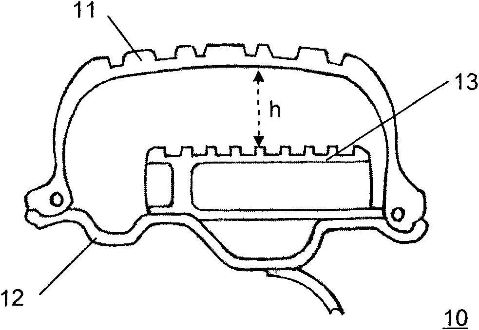
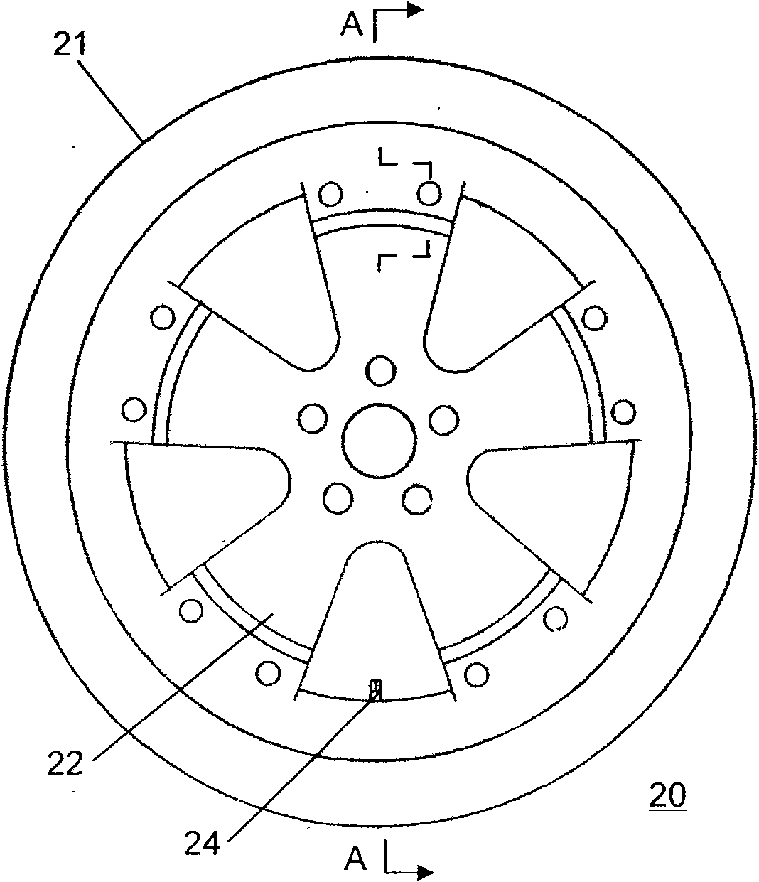
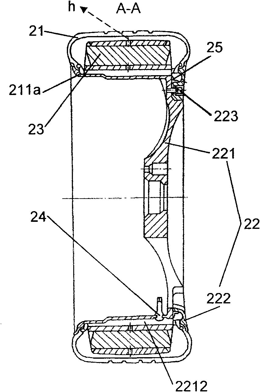
[0035] see Figure 2 ~ Figure 3 As shown, the vehicle explosion-proof safety tire 20 of the present invention is basically the same as the prior art, and also includes a cover tire 21, a rim 22 arranged on the outside of the cover tire 21, a supporting ring that is arranged in the cover tire 21 and is sleeved on the rim 22, and is connected with the tire cover 21. The valve core 24 that communicates in the tire. The difference is that the support ring is a combined support ring 23 , and the combined support ring 23 includes several layers of support rings 231 , and the several layers of support rings 231 are nested and fixed to the rim 22 . Compared with the prior art, the installation method of this combined layered matching can greatly increase the overall size of the combined support ring 23, so that under normal tire pres...


PUM


Abstract

The invention discloses an explosion-proof safety tyre of a vehicle. The tyre comprises an outer tyre, a split rim, an L-shaped sealing ring, a combined support loop and a valve core. The combined support loop comprises a plurality of layers of support rings, and a plurality of layers of support rings are sleeved layer upon layer and fixed with the rim. The size of the tyre can be increased through the combined support loop so as to furthest shorten the distance between the inner wall of the outer tyre and the outer wall of the support loop under normal tyre pressure; at tyre burst moment, the combined support loop can quickly and effectively support the outer tyre, and controls the change of the acting radius of the tyre in a smallest possible range so as to ensure the prior basic performance of the tyre, prevent accidents caused by sudden control loss of the running direction of the vehicle and avoid potential safety hazard; in addition, the split rim is favorable for mounting the large-size combined support loop by layering, and is greatly convenient for assembly and disassembly processes at the same time so that the maintenance and replacement of the tyre can be finished by adopting a common tool.

Description

technical field [0001] The invention relates to the technology of run-flat tires for vehicles, more specifically, to a run-proof safety tire for vehicles. Background technique [0002] At present, there is a class of so-called run flat tires (RSC) in the known vehicle tubeless tires, which can cause tire bursts such as tire punctures and ruptures when the vehicle is running, causing the air pressure in the tire to drop to zero. , can still travel a certain distance at the set speed. The neutron formula (PAX SYSTEM) run flat tire developed by Michelin is exactly one of them. see figure 1 Shown, this tire 10 comprises cover tire 11, is located at the rim 12 of cover tire 11 outsides, is located in cover tire 11 and is sleeved on the supporting ring 13 on the rim and communicates with the valve core with air pressure alarm in the tire (in the figure not shown). When the tire 10 is punctured or ruptured, it can still travel 200 kilometers at a speed of 80 kilometers per hour...

Claims


Application Information

Patent Timeline
Patent Type & Authority Applications(China)
IPC IPC(8): B60C17/04B60B25/02B60C23/04
CPCB60C17/041B60C17/06B60C17/066B60C2017/063B60C17/04Y10T152/10054Y10T152/10036
Inventor 吴小寅吴大钟
Owner 吴小寅
Why Eureka
Try Eureka