Heat exchanger

A technology of heat exchangers and sectors, applied in the direction of heat exchange equipment, indirect heat exchangers, heat exchanger types, etc., can solve the problems of increasing vortex, reducing effect, uneven speed, etc., to reduce maintenance costs and reduce division intervals , the effect of increasing production

Active Publication Date: 2009-12-09
LUMMUS TECH INC
View PDF0 Cites 6 Cited by
  • Summary
  • Abstract
  • Description
  • Claims
  • Application Information

AI Technical Summary

Problems solved by technology

[0012] Thus, conventional baffle arrangements as described above result in bypass flow through the baffle-housing and conduit-baffle gaps
Bypass flow reduces cross-flow heat transfer while flow maldistribution caused by significant velocity changes increases backflow and swirls in the dead zone, resulting in higher clogging rates on the shell sides
This flow maldistribution leads to high temperatures and corrosion of the peripheral conduits so that they quickly fail and thus reduce their role in the heat exchange process
Since the design of the heat exchanger is based on the uniform distribution of each tube in the entire tube bundle during the heat exchange process, these damaged tubes cannot meet this requirement and should be replaced
The high costs associated with this replacement make the heat exchanger expensive to repair
[0013] In addition, conventional arrangements can suffer from high flow-induced vibration losses due to the long pipe, typically up to 24 feet, supported by a series of baffles each spaced a large distance apart to account for problems associated with non-uniform velocity

Method used


Image

  • Heat exchanger
  • Heat exchanger
  • Heat exchanger

Examples


Embodiment Construction

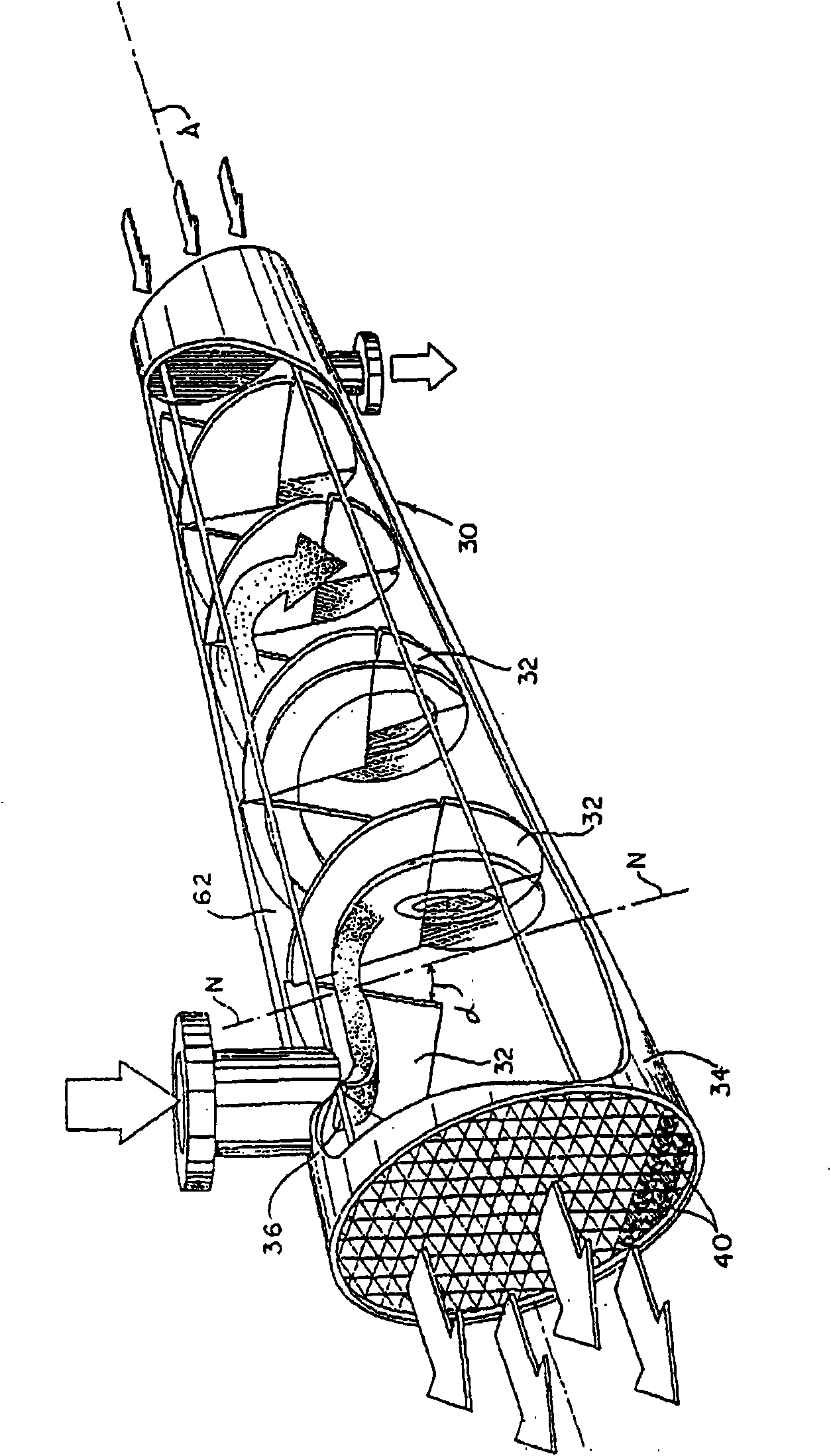
[0046] refer to figure 2 , the spiral baffle heat exchanger 30 of the present invention consists of a plurality of sector baffles 32, each of which is placed at an angle λ with respect to the normal line N-N to the longitudinal axis A-A of the shell 34. Thus, sector baffles 32 (hereafter baffles) direct the cross flow 36 at the sides of the shell in a helical pattern and in a reduced unsupported pipe distance between the baffles. This results in true cross flow on the housing sides with efficient transfer of available pressure drop to heat transfer and reduces damage as vibration of another fluid passing through conduit 40 is minimized. This eliminates dead spots to block cross flow 36 and substantially eliminates the dissipative energy of eddies or backmixing. While the baffles 32 are straight as shown in the figures, opposite sides of each baffle may be curved to direct the cross flow 36 along a helical pattern.

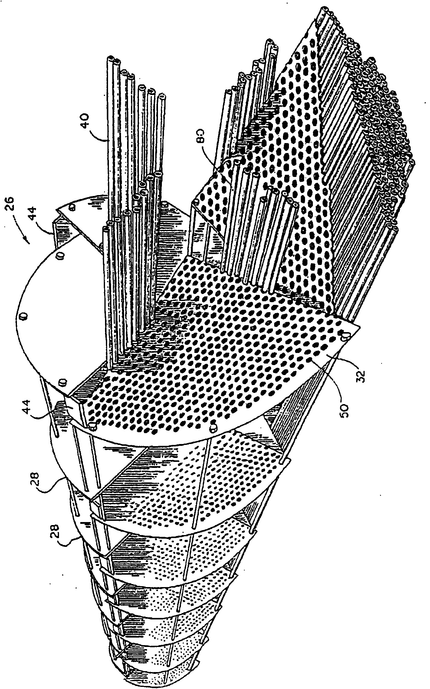
[0047] Such as image 3 and 4 As shown in , the baffle h...


PUM


Abstract

A heat exchanger is configured to have quadrant shaped baffles positioned at an angle to a longitudinal axis of shell for guiding cross-flow of fluid into a helical pattern while maintaining substantially uniform velocity of the cross-flow. Each of the quadrant-shaped baffles has a pair of flanks converging toward one another from a respective outer edge, which has spaced apart extending end portions each overhanging a respective one of the pair of flanks and configured to overlap the extending portion of an adjacent quadrant-shaped baffle in the desired position of the quadrant-shaped baffles. The extending end portions each are provided with at least one of the plurality of holes aligned with a respective hole of the extending portion of the adjacent quadrant-shaped baffle in the desired position of the quadrant-shaped baffles, wherein as the holes formed in the extending portions of the adjacent baffles are traversed by a respective pipe to secure the desired position of the quadrant-shaped baffles.

Description

[0001] This application is a divisional application of a Chinese patent application with an application date of November 21, 2003, an application number of 200310119681.5, and an invention name of "heat exchanger". technical field [0002] The present invention relates to a heat exchanger, more particularly but not exclusively to a shell-and-tube heat exchanger configured to provide uniform flow of fluid along helical channels and maximize heat transfer. Background technique [0003] The main goals of long-term efforts to achieve maximum output from heat exchange and / or heat generating devices are to achieve the following: [0004] Higher heat transfer efficiency; [0005] lower pressure drop; [0006] Enhanced performance; [0007] Effective anti-vibration protection; and [0008] Reduced installation and maintenance costs. [0009] Whether in offshore mining, refining, power, petrochemical or paper and food industries, heat exchangers are often a central part of the ab...

Claims


Application Information

Patent Timeline
Patent Type & Authority Applications(China)
IPC IPC(8): F28D7/10F28F9/22F28D7/16
CPCF28F9/22F28D7/1607F28F2009/228F28F2225/00F28D7/02F28D7/16
Inventor 巴希尔·I·马斯特克里希南·S·丘纳恩戈德文卡特斯瓦兰·普什帕内森
Owner LUMMUS TECH INC
Why Eureka
Try Eureka