Permanent magnet type non-contact vibration exciter and excitation method thereof

A non-contact, vibration exciter technology, applied in the direction of instruments, electromagnets, vibration testing, etc., can solve problems such as difficult to apply to moving workpieces, complex structures, structural boundary changes, etc., to achieve the effect of ensuring integrity

Inactive Publication Date: 2009-12-09
NANJING UNIV OF AERONAUTICS & ASTRONAUTICS
View PDF0 Cites 17 Cited by
  • Summary
  • Abstract
  • Description
  • Claims
  • Application Information

AI Technical Summary

Problems solved by technology

The former destroys the structure, although the latter does not destroy the structure, but the prestress may be generated when the vibrator is installed, the boundary of the structure changes, and thus the stiffness changes
[0010] 2. It cannot be used for moving structures. When the test piece moves, the exciter must follow the structure movement, which is difficult to achieve
[0013] 1. To realize the adjustable direction of the exciting force, it is necessary to install a permanent magnet at the force point of the structure, and then adjust the direction of the current in the coil to achieve this. This will destroy the structure and change the mass distribution of the structure. This point has something to do with the original intention of non-contact Contradictory; if no permanent magnet is installed, this type of exciter can only produce a unidirectional force on the ferromagnetic structure
[0014] 2. Need a special current control system, the structure is more complicated
[0015] 3. It is difficult to apply to the moving workpiece. As mentioned in 1, the workpiece needs to be installed with a permanent magnet. When the workpiece moves, the coil is required to follow the permanent magnet movement, or the area of ​​the permanent magnet is large enough to ensure that the coil can be used during the movement of the workpiece. interact with it

Method used


Image

  • Permanent magnet type non-contact vibration exciter and excitation method thereof

Examples


Embodiment Construction

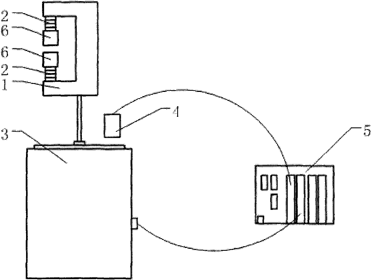
[0027] Such as figure 1 Shown, device vibration generator 3 (as electromagnetic exciter) of the present invention, the signal generator 5 that is connected with vibration generator, also comprise the C-type clamp 1 that is connected with vibration generator, C-type clamp is symmetrical Strong magnets 2 and armatures 6 are installed in the two clamping arms, and the workpiece is located between the gaps between the two armatures. It also includes a displacement sensor 4 for detecting displacement changes of the C-shaped clamp.

[0028] The process of generating the exciting force of the permanent magnet non-contact vibrator of the present invention is as follows: the signal generator 5 sends a voltage signal to the vibration generator 3, and the vibration generator produces a certain displacement, so that the distance between the armature 6 and the surface of the structure changes, thereby generating Exciting forces of different magnitudes and directions. When installing the f...


PUM


Abstract

The invention discloses a permanent magnet type non-contact vibration exciter and an excitation method thereof; wherein the vibration exciter comprises a traditional vibration generator, a C type magnetic clamp, strong magnet blocks and armature blocks. A C type magnetic briquette is arranged on an electromagnetic vibration exciter, the two ends of the C type magnetic briquette are respectively provided with the strong magnet blocks and the armature blocks which are absorbed at the terminals of the strong magnet blocks. Actual displacement output of the armature block is sensed by a displacement sensor for feedback compensation, accurate displacement output is realized, and the aim of controlling exciting force is achieved. The invention has the advantages that the structure is simple, assembly and disassembly are convenient, processing is easy, and the vibration exciter can be used for excitation of a moving structure and can realize non-contact excitation on ferromagnetic metal structures, etc.

Description

technical field [0001] The invention belongs to the field of mechanical vibration and testing, in particular to a permanent magnet-based non-contact vibrator and a vibrating method thereof. Background technique [0002] The exciter is a device attached to some machinery and equipment to generate excitation force, and is an important part of using mechanical vibration. The vibrator can make the excited object obtain a certain form and size of vibration, so as to perform vibration and strength tests on the object, or to calibrate vibration testing instruments and sensors. The vibrator can also be used as an exciting part to form a vibrating machine to realize the conveying, screening, compacting, forming and tamping of soil and gravel for materials or objects. [0003] Today's mainstream contact vibrators include inertial electric, electromagnetic, electro-hydraulic, pneumatic and hydraulic. The exciter can produce unidirectional or multidirectional, harmonic or non-harmonic...

Claims


Application Information

Patent Timeline
Patent Type & Authority Applications(China)
IPC IPC(8): H01F7/08G01M7/02G01H17/00
Inventor 王亮陈怀海贺旭东
Owner NANJING UNIV OF AERONAUTICS & ASTRONAUTICS
Why Eureka
Try Eureka