Inner wall spraying robot system and inner wall spraying method

A spraying robot and robot technology, applied in the field of robotics, can solve the problems of bumping of the sprayed object, narrow inner wall space, poor flexibility, etc., and achieve the effects of preventing interference, accurate positioning, and convenient movement.

Active Publication Date: 2009-12-16
TSINGHUA UNIV +1
View PDF2 Cites 32 Cited by
  • Summary
  • Abstract
  • Description
  • Claims
  • Application Information

AI Technical Summary

Problems solved by technology

[0003]At present, the spraying robots designed by the world's major robot companies only work on the outer wall of the pipeline. If the spraying robot is used to spray the inner wall of complex workpieces, it has the following Disadvantages: 1) When the spraying robot sprays the curved surface of the inner wall, due to the limitation of the shape of the workpiece, it is difficult for the mechanical arm to enter the interior of the complex workpiece, and it is difficult to adjust the distance and angle between the nozzle and the curved wall to appropriate parameters, so the coating is uniform degrees affected
2) prone to collision
Due to the narrow inner wall space of complex workpieces, it is difficult to avoid the constraint obstacles of the task space with straight-arm robots, so it is easy to collide with the object to be sprayed
The above defects are due to the non-redundant degree of freedom design of the prior art spraying robots, which makes the robot unable to avoid obstacles in the task space and has poor flexibility
[0004] Publication No. CN101337352A Chinese patent application "inner surface spraying robot" is limited to the inner wall spraying of box body parts, does not involve the spraying of narrow and long special-shaped pipes; the announcement number is CN2268831Y Although the Chinese patent "Spray anti-corrosion device for underground pipelines" involves spraying the inner walls of pipelines, it is limited to standard cylindrical short pipelines, and does not involve special-shaped narrow and long pipelines.

Method used


Image

  • Inner wall spraying robot system and inner wall spraying method
  • Inner wall spraying robot system and inner wall spraying method
  • Inner wall spraying robot system and inner wall spraying method

Examples


Embodiment Construction

[0029] The specific embodiments of the present invention will be described in further detail below in conjunction with the drawings and embodiments. The following examples are used to illustrate the present invention, but not to limit the scope of the present invention.

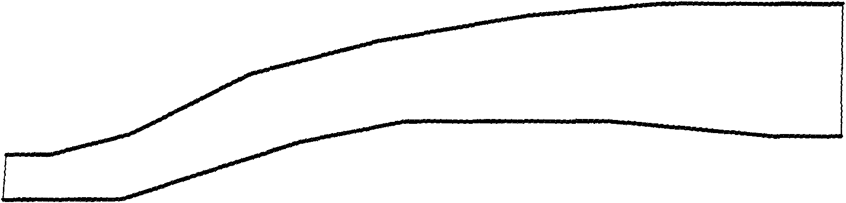
[0030] figure 1 It is a schematic diagram of a special-shaped long and narrow pipe for spraying by a robot according to an embodiment of the present invention. Such as figure 1 As shown, it is a typical variable cross-section S-shaped narrow and long pipeline, and its inner wall spraying operation is difficult to complete with existing robots.

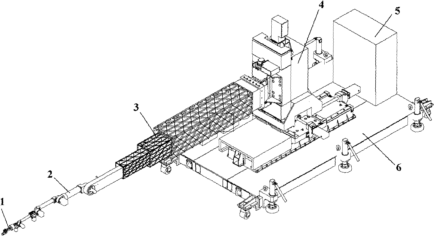
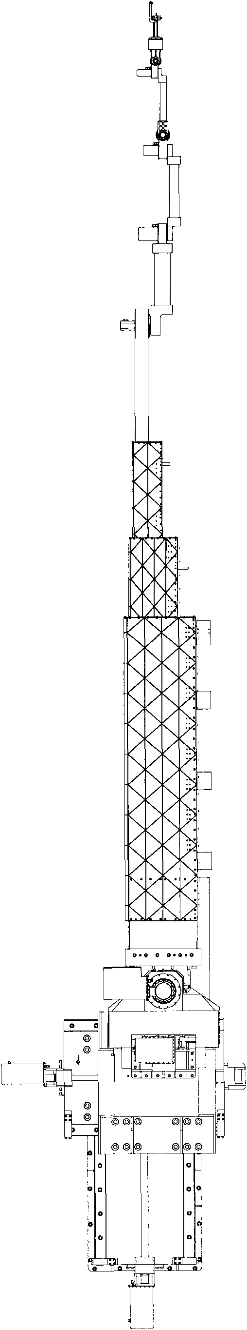
[0031] figure 2 Is a perspective view of the system of the embodiment of the present invention; Figure 3a , 3b They are a top view and a side view of the system of the embodiment of the present invention; Figure 4 Is a perspective view of the base and pneumatic transport vehicle assembly in the system of the embodiment of the present invention; Figure 5 It is a sc...


PUM


Abstract

The invention discloses an inner wall spraying robot system and an inner wall spraying method. The system comprises a robot and an air cushion transport vehicle, wherein the robot is used for finishing the spraying work; the robot comprises a spray gun, a crank arm, a telescopic arm and a base, which are connected in turn; the sum of freedom degrees of the spray gun, the crank arm, the telescopic arm and the base is not less than 6; and the robot is arranged on the air cushion transport vehicle, the air cushion transport vehicle comprises an air bag positioned at the bottom thereof, and the air bag is used for floating the air cushion transport vehicle so as to coarsely position the system before the system enters a working area. The technical proposal of the invention realizes spraying work for the inner wall of a special-shaped long and narrow pipeline through multi-redundant freedom degree design for the robot, and improves the efficiency of preparation work before the spraying work.

Description

Technical field [0001] The invention relates to the technical field of robots, and specifically designs a multi-redundant air-floating mobile robot system for spraying on the inner wall of a special-shaped narrow and long tube and an inner wall spraying method. Background technique [0002] In the field of special industry (especially in the field of aerospace), the inner walls of long and narrow tubes of many complex workpieces need to be sprayed. Because the inner surfaces of these long and narrow tubes are relatively complex and the internal space is extremely small, it is difficult for spraying technicians to enter, so automatic spraying must be used by robots. [0003] At present, the spraying robots designed by major robot companies in the world only work on the outer wall of the pipeline. If the spraying robot is used to spray the inner wall of complex workpieces, it has the following disadvantages: 1) When the spraying robot sprays the inner wall surface, due to the workp...

Claims


Application Information

Patent Timeline
Patent Type & Authority Applications(China)
IPC IPC(8): B05B13/00B05B13/06B05B15/00B05C7/02B05C5/00B05C21/00B25J5/04F16L55/30F16L101/16
Inventor 陈恳李金泉付成龙杨向东曹文敦付铁张传清陈雁邵君奕陈明启路敦民吴丹杨东超刘莉刘宗政徐家球郑林斌王力强颜华
Owner TSINGHUA UNIV
Why Eureka
Try Eureka