This helps you quickly interpret patents by identifying the three key elements:
Problems solved by technology
Method used
Benefits of technology
Problems solved by technology
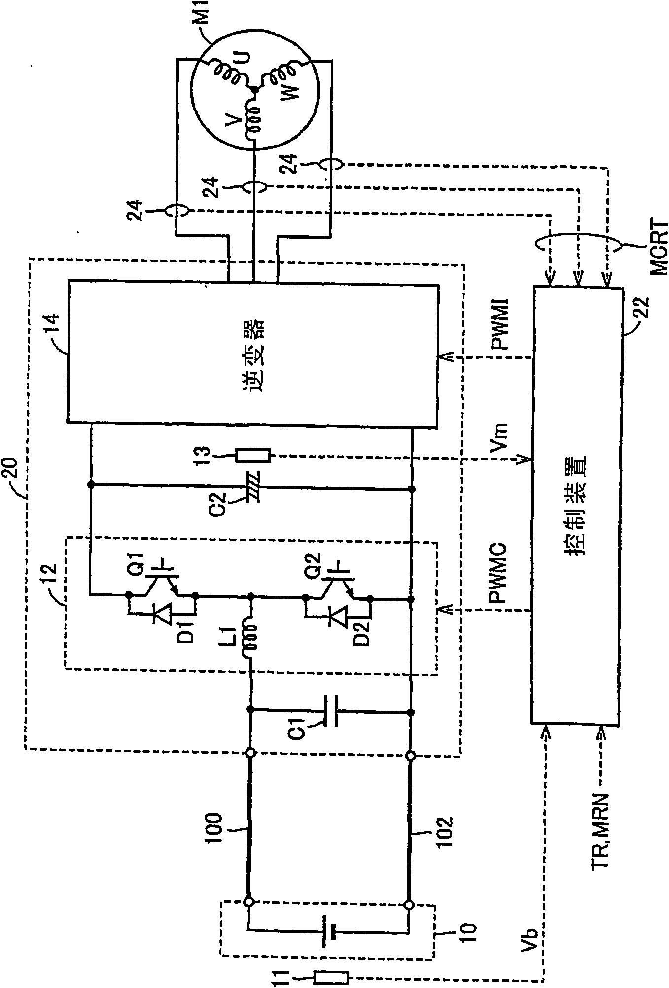
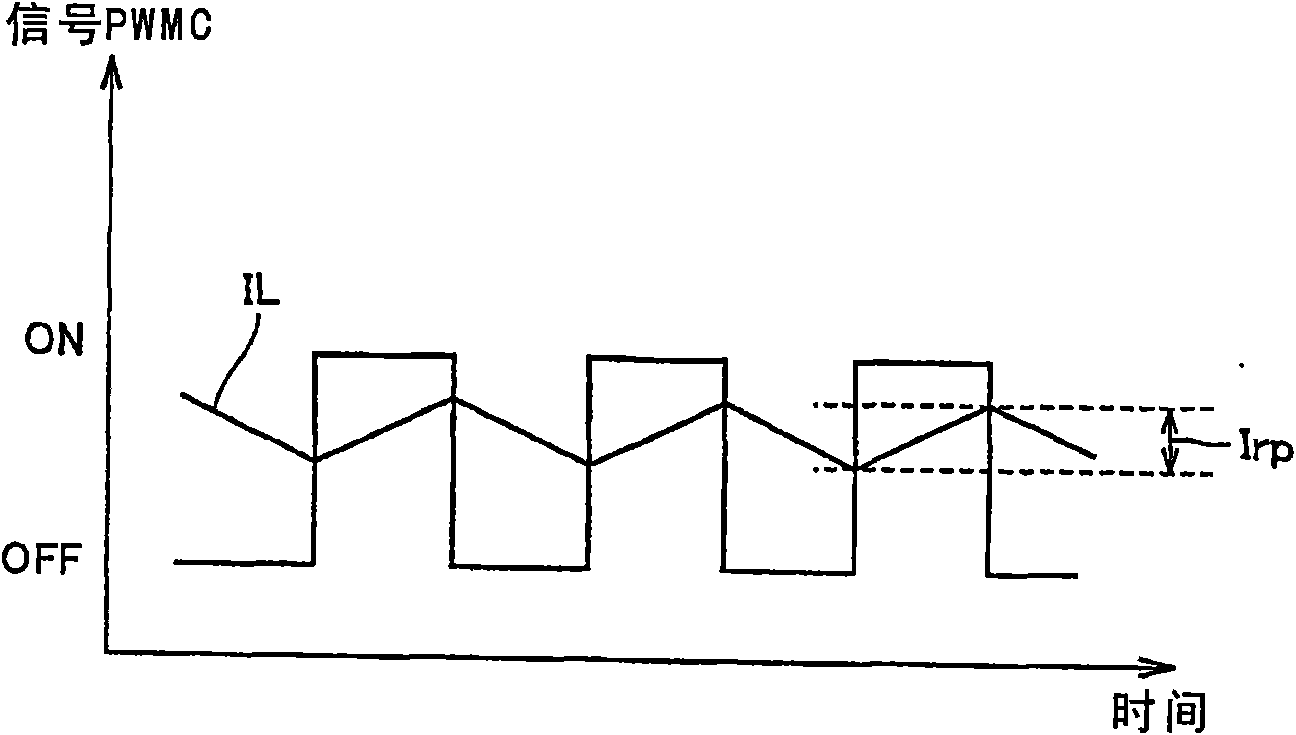
[0005] However, in a configuration using a booster circuit as disclosed in JP-A-10-066383, when the transistors of the booster circuit perform switching operations, an alternating current (hereinafter also referred to as “current”) depending on the switching frequency is generated. ripple current)
Due to the influence of this ripple current, the battery vibrates, which may cause noise
Method used
Image
Click on the blue label to locate the original text in one second.
Reading with bidirectional positioning of images and text.
Examples
Embodiment approach 1
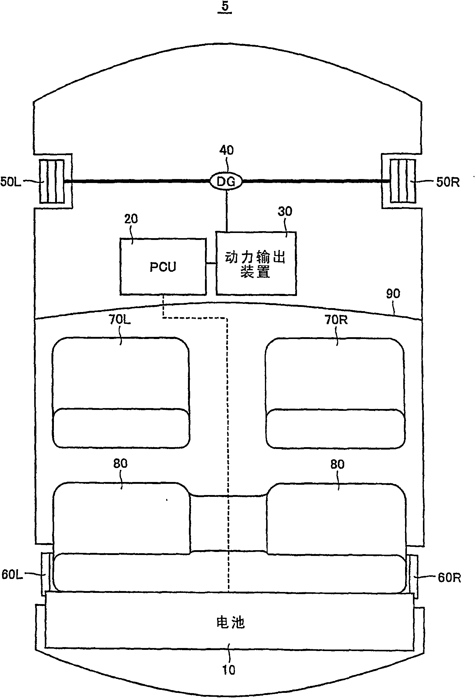
[0042] figure 1 It is a schematic block diagram showing the overall configuration of a hybrid vehicle shown as an example of installation of the load driving device in the present invention.
[0043] refer to figure 1 , the hybrid vehicle 5 includes a battery 10, a PCU (Power Control Unit) 20, a power output device 30, a differential gear (DG: Differential Gear) 40, front wheels 50L, 50R, rear wheels 60L, 60R, front seats Chairs 70L, 70R and rear seat 80.
[0044] The battery 10 is arranged behind the rear seat 80 . Furthermore, battery 10 is electrically connected to PCU 20 . The PCU 20 is arranged, for example, using the lower regions of the front seats 70L, 70R, that is, the underfloor region. The power output device 30 is arranged in the engine compartment on the front side of the instrument panel 90 . PCU 20 is electrically connected to power output device 30 . The power output device 30 is connected to the DG40.
[0045] Battery 10 as a DC power supply is constitu...
Embodiment approach 2
[0125] Figure 11 It is a perspective view of a hybrid vehicle 5 to which the power cable wiring structure in Embodiment 2 of the present invention is applied.
[0126] refer to Figure 11 , in the hybrid vehicle 5, the latch outer reinforcement 200L and the door belt line reinforcement 400 forming a part of the left side of the vehicle in the vehicle width direction extend in the vehicle front-rear direction. The latch outer reinforcement 200L and the door belt line reinforcement 400 constitute a vehicle left side frame member.
[0127] In this vehicle body structure, a part of the section of the power cable 102 along the vehicle front-rear direction is arranged along the inner side surface of the buckle outer reinforcement 200L in the vehicle width direction. In addition, the section of the part of the power cable 102 and Figure 8 As described above, it is arranged in a space formed between the vehicle width direction inner surface of the latch outer reinforcement 200L a...
PUM
Abstract
A hybrid automobile (5) has rocker outer reinforcements (200R, 200L) which are frame members on vehicle side portions and are placed on both sides in the width direction of the vehicle and extended in the front-rear direction of the vehicle. An electric power cable (100) is placed so that a part of the cable in the front-rear direction of the vehicle is along an inner surface in the vehicle widthdirection of the rocker outer reinforcement (200R). An electric power cable (102) is placed so that a part of the cable in the front-rear direction of the vehicle is along an inner surface in the vehicle width direction of the rocker outer reinforcement (200L). Further, the electric power cables (100, 102) are arranged in spaces each formed between the rocker outer reinforcement (200R, 200L) and a center body pillar that is an energy absorption member in a side collision of the vehicle.
Description
technical field [0001] The present invention relates to a load driving device, and more particularly, to a load driving device including a switching element, which receives electric power from a battery and drives an electric load. Background technique [0002] Japanese Patent Document No. 10-066383 discloses a drive control device for a permanent magnet type synchronous motor (PM motor). The drive control device includes a voltage boosting circuit that boosts the battery voltage according to a command before it is supplied to the power converter, and causes the voltage boosting circuit to perform a voltage boosting operation so that the boosted voltage value exceeds what is required to realize the target operating point of the PM motor. A unit of the DC terminal side voltage of the power converter. [0003] In this drive control device, when the target operating point of the PM motor is on the higher rotation side than the output-capable range under the current battery vol...
Claims
Application Information
Patent Timeline
Application Date:The date an application was filed.
Publication Date:The date a patent or application was officially published.
First Publication Date:The earliest publication date of a patent with the same application number.
Issue Date:Publication date of the patent grant document.
PCT Entry Date:The Entry date of PCT National Phase.
Estimated Expiry Date:The statutory expiry date of a patent right according to the Patent Law, and it is the longest term of protection that the patent right can achieve without the termination of the patent right due to other reasons(Term extension factor has been taken into account ).
Invalid Date:Actual expiry date is based on effective date or publication date of legal transaction data of invalid patent.