Vehicular solar energy generating set

A power generation device and solar energy technology, applied in the direction of solar thermal power generation, solar thermal devices, heating devices, etc., can solve the problems of high cost, no practical value, and unsuitable for popularization and application of vehicle-mounted power stations, and achieve convenient production and installation Erection, simple structure, and the effect of improving utilization efficiency

Inactive Publication Date: 2009-12-23
TAIZHOU LIFA ELECTRONICS
View PDF1 Cites 3 Cited by
  • Summary
  • Abstract
  • Description
  • Claims
  • Application Information

AI Technical Summary

Problems solved by technology

The vehicle-mounted power station has high cost, complex structure, no practical value, and is not suitable for popularization and application

Method used


Image

  • Vehicular solar energy generating set
  • Vehicular solar energy generating set

Examples


Embodiment 1

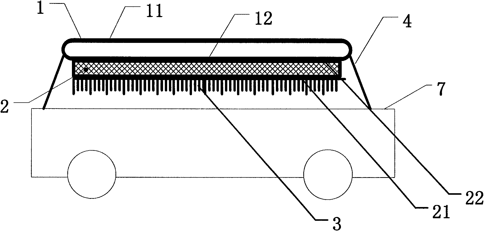
[0021] see figure 1 , the vehicle-mounted solar power generation device of the present invention includes a solar power generation assembly erected on the roof 7 by a support structure 4 fixed on the roof 7, and the solar power generation assembly includes: a solar heat collector 1 at the top, a thermoelectric cell 2 and heat sink 3.

[0022] The interior of the solar heat collector 1 is mainly composed of the upper glass 11 and the lower glass 12 to form a cylindrical vacuum space, forming a solar vacuum heat collection tube; the inner wall surface of the upper glass 11 is coated with a solar absorbing film.

[0023] The hot end 22 of the thermoelectric battery 2 is in contact with the solar heat collector 1 for heat exchange, and the cold end 21 of the thermoelectric battery 2 is in contact with the cooling fin 3 for heat exchange.

[0024] The cooling fin 3 is located at the bottom of the solar power generation module, and there is a cooling gap between the roof 7 and the ...

Embodiment 2

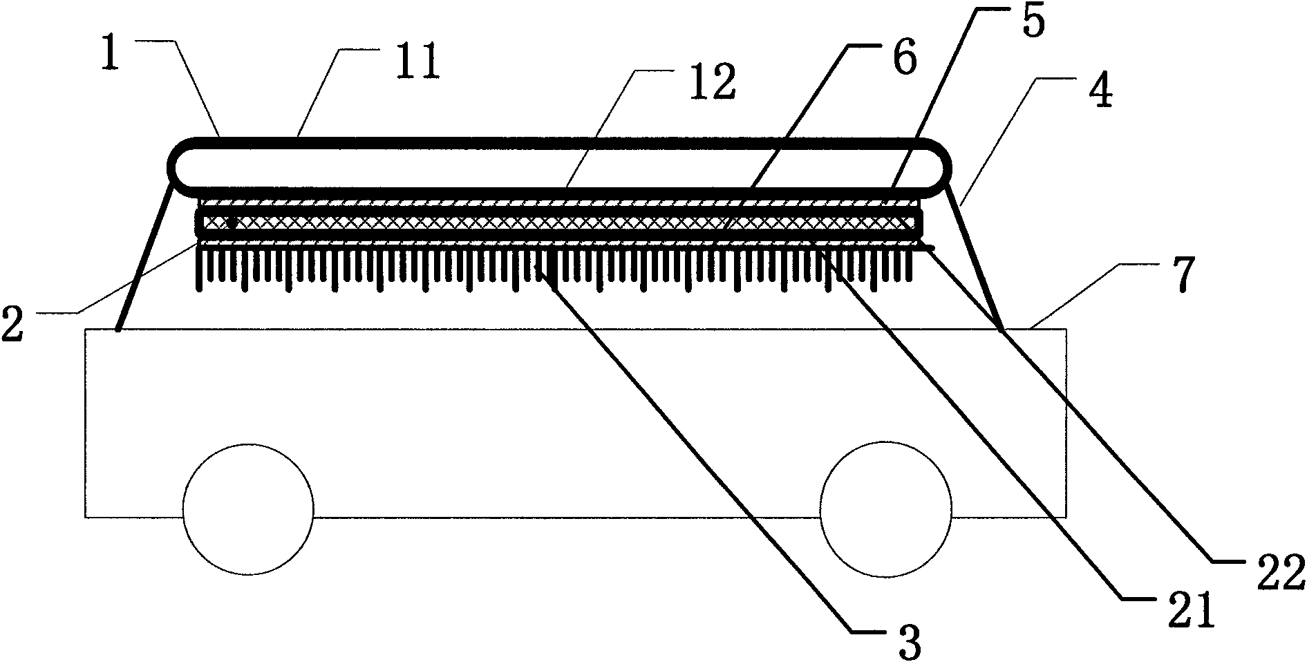
[0027] see figure 2 , in the vehicle-mounted solar power generation device of the present invention, a layer of heat-conducting silica gel 5 is coated between the hot end 22 of the thermoelectric battery 2 and the contact heat exchange part of the solar heat collector 1, and between the cold end 21 of the thermoelectric battery 2 and the heat sink 3 A layer of thermal silica gel 6 is coated between them. Other settings are the same as in Example 1.

[0028] When the device is working, the solar vacuum heat collecting tube converts direct sunlight, scattering and sunlight reflected by other reflective surfaces into heat, and transfers the heat to the hot end 22 of the thermoelectric battery 2 through the heat-conducting silica gel 5, so that the thermoelectric battery 2 starts to work and generates electric energy . In order to make the thermoelectric battery 2 work normally, there should be sufficient temperature difference between the hot end 22 and the cold end 21 of the ...


PUM


Abstract

The invention discloses a vehicular solar energy generating set comprising a solar energy generating assembly erected on the top of a vehicle. The solar energy generating assembly comprises a solar energy heat collector arranged at the top, a heat sink and a thermoelectric cell, wherein, the hot end and the cold end of the thermoelectric cell respectively exchange heat with the solar energy heat collector and the heat sink. A heat dissipation gap is left between the heat sink and the top of the vehicle, the heat sink can also be provided with a plurality of slotting structures, and the slotting direction is the same with vehicle movement direction. The generating set of the invention improves the usage efficiency of solar energy, and generating cost is lower to below 0.4 yuan/degree. The generating set of the invention has simple structure and convenient manufacture and installation, and can play the function of shading sun for vehicle if being arranged at the top of the vehicle.

Description

technical field [0001] The invention belongs to the field of development and utilization of new energy, and in particular relates to a vehicle-mounted solar power generation device. Background technique [0002] Traditional solar power generation technology has the problem of high cost. In recent years, people are studying the use of photovoltaic cells for solar power generation. However, due to the cost limitation of semiconductor silicon materials used to produce solar photovoltaic cells, there is still a high cost of using photovoltaic cells for solar power generation. question. The use of thermoelectric batteries (also known as thermoelectric power generation sheets) for power generation can solve the problem of high cost of traditional solar power generation technology. Compared with photovoltaic cells, thermoelectric cells have the advantage of low cost. Thermoelectric cells can not only use visible light, but also use the heat of invisible light in the solar spectrum...

Claims


Application Information

Patent Timeline
Patent Type & Authority Applications(China)
IPC IPC(8): H02N11/00F24J2/00F24J2/48F28F3/02
CPCY02E10/40
Inventor 王勇余德永
Owner TAIZHOU LIFA ELECTRONICS
Why Eureka
Try Eureka