Drive circuit of fluorescent tube

A technology for driving circuits and fluorescent tubes, applied in the direction of light sources, electric light sources, electrical components, etc., to achieve the effect of reducing pins, reducing external electronic components, and simplifying circuit design

Inactive Publication Date: 2009-12-23
NIKO SEMICON
View PDF0 Cites 9 Cited by
  • Summary
  • Abstract
  • Description
  • Claims
  • Application Information

AI Technical Summary

Problems solved by technology

However, the number of pins of the PWM controller and the number of electronic components used are still too many, so how to reduce the number of pins of the PWM controller and the number of electronic components to further simplify the circuit design is still the current cold cathode ray lamp. An important direction for the research and development of tube drive circuits

Method used


Image

  • Drive circuit of fluorescent tube
  • Drive circuit of fluorescent tube
  • Drive circuit of fluorescent tube

Examples


Embodiment Construction

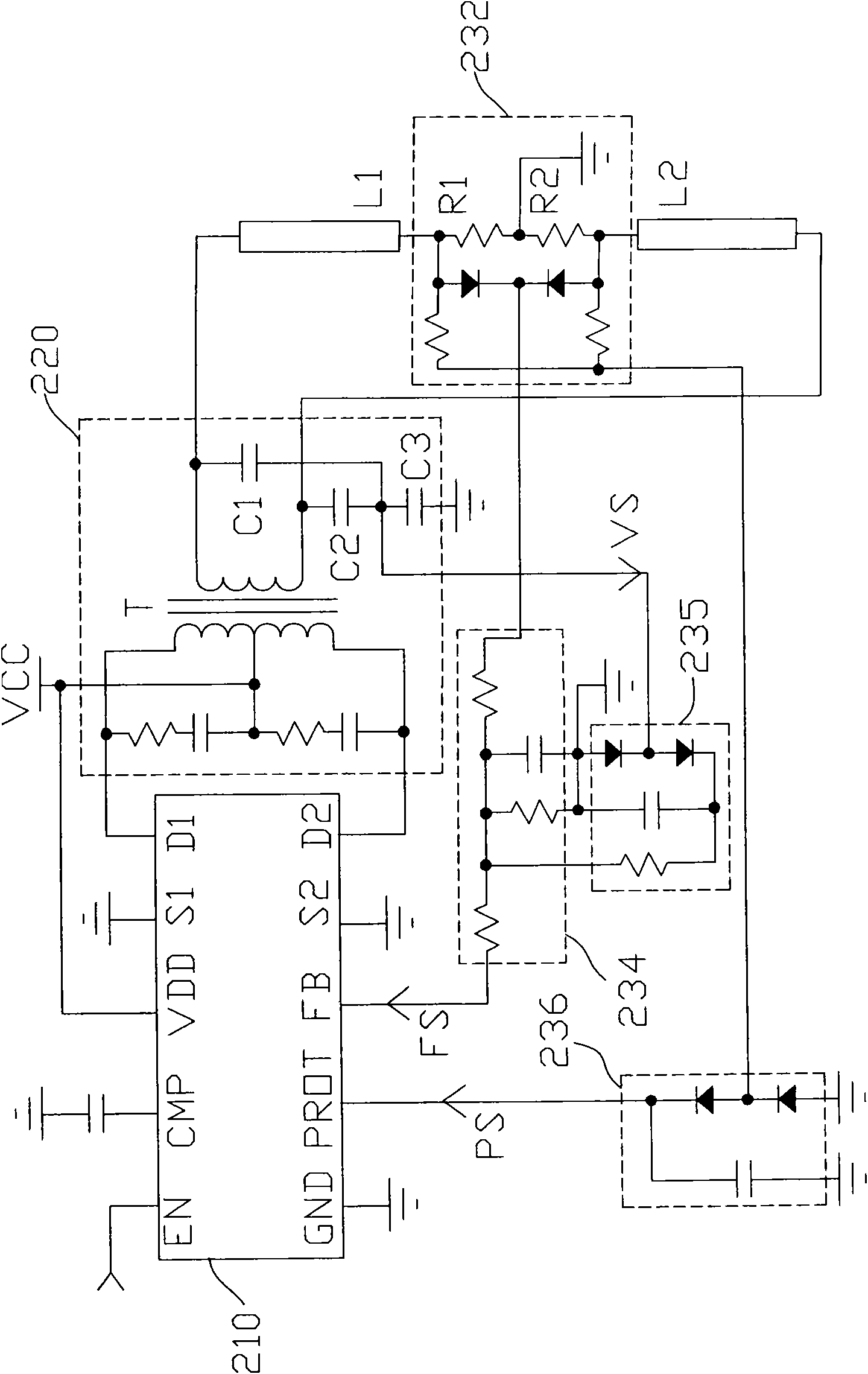
[0047] Please refer to figure 2 , is a schematic circuit diagram of a multi-lamp driving circuit according to the first embodiment of the present invention, including a controller 210, a resonant module 220, a lamp module and a detection device. Wherein, the lamp module includes lamps L1 and L2 , and the detection device includes a detection unit 232 , a current detection feedback unit 234 , a voltage detection feedback unit 235 and a protection detection feedback unit 236 . The resonant module 220 has a primary side and a secondary side, and mainly includes a transformer T and resonant capacitors C1 - C3 . The primary side of the transformer T has two connection terminals and a central tap terminal, the central tap terminal is connected to an input voltage VCC, and the two connection terminals are respectively connected to the pins D1 and D2 of the controller 210 . In this way, the resonant module 220 can convert the power of the input voltage VCC received by the primary si...


PUM


Abstract

The invention discloses a drive circuit of a fluorescent tube, which comprises a resonance module, a tube module, a detection device and a controller, wherein the resonance module comprises a primary side and a secondary side so as to convert the electric power of input voltage received by the primary side into an AC signal and output the AC signal from the secondary side; the resonance module also comprises a transformer, and a primary side of the transformer is provided with two connecting ends and a central tap end; the tube module comprises a plurality of tubes and is coupled to the secondary side of the resonance module so as to receive the AC signal; the detection device and the tube module are connected in series to the secondary side of the resonance module; one end of the detection device is connected with a reference potential end, and the detection device generates a current detection signal and a protection feedback signal according to current flowing through the tubes; the controller comprises two semiconductor switches which are mutually connected through one end of each semiconductor switch, and the other ends are respectively coupled to the two connecting ends of the primary side of the transformer; a base pin of the controller receives the current detection signal so as to achieve feedback control, while the other base pin receives the protection feedback signal so as to achieve protection control, thereby simplifying the circuit design.

Description

technical field [0001] The invention relates to a fluorescent tube driving circuit, in particular to a multi-lamp driving circuit with built-in MOSFET (Metal Oxide Semiconductor Field Effect Transistor). Background technique [0002] The LCD panel backlight device uses a high-frequency AC sine wave power supply to supply the energy for the cold cathode ray lamp (CCFL, Cold Cathode Fluorescent Lamp) to emit light, so a DC-to-AC converter circuit (DC / AC Inverter) is used to achieve energy conversion the goal of. A general cold cathode ray lamp drive circuit uses a resonant module to convert a DC voltage into an AC voltage to drive a cold cathode ray lamp to emit light, and detects the driving voltage and current of the cold cathode ray lamp through a voltage and current detection circuit. drive current. A pulse width modulation (PWM, Pulse Width Modulated) controller receives the voltage detection signal and the current detection signal for stabilizing the light emission of ...

Claims


Application Information

Patent Timeline
Patent Type & Authority Applications(China)
IPC IPC(8): H05B41/298G09G3/36G05F1/12
Inventor 王政雄
Owner NIKO SEMICON
Why Eureka
Try Eureka