
Universal cutting machine

A cutting machine and universal technology, applied in the direction of metal sawing equipment, sawing equipment, metal processing equipment, etc., to achieve the effect of improving work efficiency and quality, high quality, and fast speed

Inactive Publication Date: 2011-09-07
顾伟国
View PDF0 Cites 0 Cited by
  • Summary
  • Abstract
  • Description
  • Claims
  • Application Information

AI Technical Summary

Problems solved by technology

Greatly improve work efficiency and construction quality

Method used


Image

  • Universal cutting machine
  • Universal cutting machine
  • Universal cutting machine

Examples


Embodiment Construction

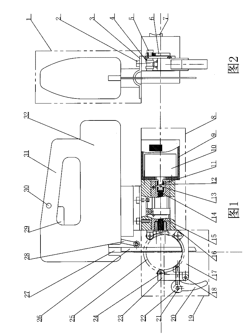
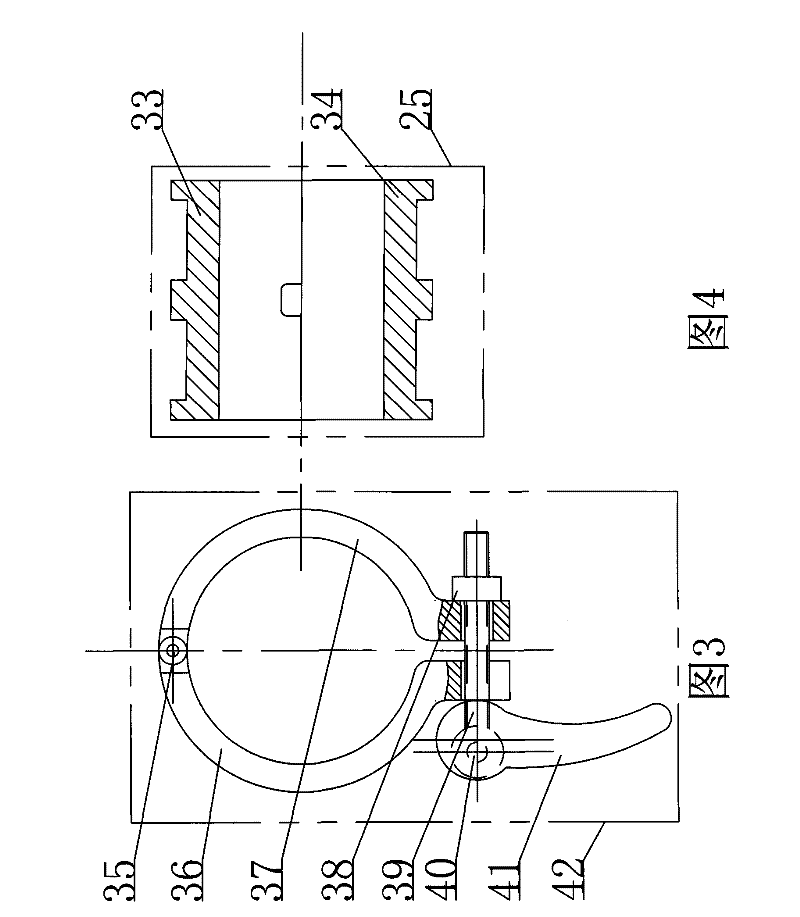
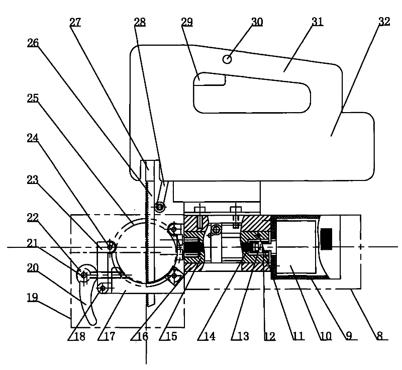
[0016] Depend on Figure 4 It can be seen that first press the mold (25) and clamp the mold (25), the mold (25) is composed of upper and lower molds with positioning steps, and blocks the workpiece to be cut. The shape of the inner hole of the mold (25) is according to the shape of the workpiece Depends, by image 3 It can be seen that the inner circular arc of the beam mold clamp assembly (42) is the same as the shape of the mold outer groove, adjust the adjustment nut (38) and turn the wrench (41) with an eccentric wheel structure to compress the left beam mold clamp (36) and The right bundle mold card (37), clamps mold (25) and workpiece. Depend on figure 1 It can be seen that, after the clamp assembly (19) is snapped into the outer groove of the mold (25), the wrench (20) with the eccentric wheel is pulled to compress the rolling wheel (4) on the movable clamp (23), three Group rolling wheel encircles mould, has three or more groups of rolling wheels (4) that can roll i...


PUM


Abstract

The invention discloses a novel universal cutting machine. The prior cutting operation is changed through a novel working mode and a novel mechanical structure. The universal cutting machine consists of a reciprocating cutting module, a stroke control module, a fixture module, a mold, and a mold constraint fixture module, wherein the mold locks a workpiece to be cut; the mold constraint fixture module firmly locks the mold and the workpiece; the fixture module is provided with three groups or a plurality of groups of rolling wheels which can roll in an outer groove of the mold; the rolling wheels on the fixture module are firmly pressed to ensure that three groups of the rolling wheels surround the mold; the fixture module is fixedly connected with a sliding block in the stroke control module; the sliding block can move back and forth in a sliding block sleeve through the fit that a motor drives a lead screw; a stroke positioning block can move and be fixed on the sliding block sleeveand block a positioning pin to control the stroke of the sliding block; the sliding block sleeve is provided with a graduated scale for indicating the stroke; and the reciprocating cutting module is to drive a saw blade fixture by the motor to make a saw blade perform reciprocating motion and cut the workpiece by controlling the stroke control module, and can also perform rotary cutting through the rolling of the rolling wheels on the mold.

Description

Technical field: [0001] This product involves a new workpiece cutting method and mechanical structure, which can be easily and standardly completed when cutting precision and cutting the outer layer of the workpiece are required. Background technique: [0002] At present, under the background of the rapid development of engineering units such as electric power and railways, the requirements for project quality and work efficiency are getting higher and higher. There are more and more on-site, field, and high-altitude operations. The work of cutting workpieces is not only large in quantity but also high in quality. It is difficult to guarantee. For example, in electric power engineering, it is often encountered when cutting aluminum stranded wires with steel cores. The requirement is to cut off the outer aluminum wire layer and retain the middle bearing steel core without cutting the steel core. The level must be very high, and most of the site uses hand saws, which is troubl...

Claims


Application Information

Patent Timeline
Patent Type & Authority Patents(China)
IPC IPC(8): B23D49/00
Inventor 顾伟国
Owner 顾伟国
Learn More