Die-cutting cutter structure improved die-cutting machine for wound roll materials

A die-cutting machine and coil technology, applied in metal processing and other directions, can solve the problems of incompatibility with small batch production, high cost of die-cutting tools, low die-cutting quality, etc. The production period and the effect of reducing the work intensity

Inactive Publication Date: 2009-12-30
杜建刚
View PDF0 Cites 2 Cited by
  • Summary
  • Abstract
  • Description
  • Claims
  • Application Information

AI Technical Summary

Problems solved by technology

The die-cutting machine of the present invention can solve the problem of high cost of die-cutting tools, long production cycle, poor durability, complicated machine adjustment, heavy machine, low die-cutting quality, instability, low die-cutting speed, and not suitable for small batches in the prior art. Technical problems in production, etc.

Method used


Image

  • Die-cutting cutter structure improved die-cutting machine for wound roll materials
  • Die-cutting cutter structure improved die-cutting machine for wound roll materials
  • Die-cutting cutter structure improved die-cutting machine for wound roll materials

Examples


Embodiment Construction

[0020] The present invention will be described in further detail below in conjunction with the accompanying drawings and specific embodiments.

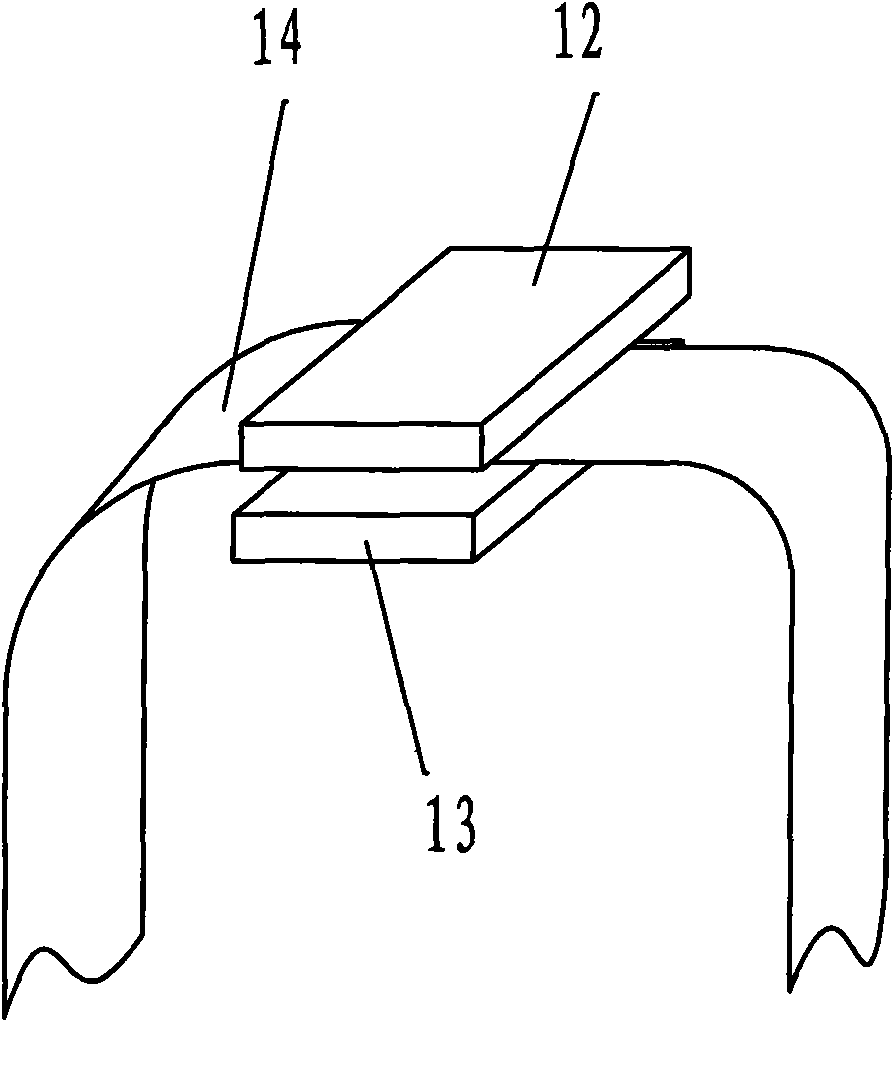
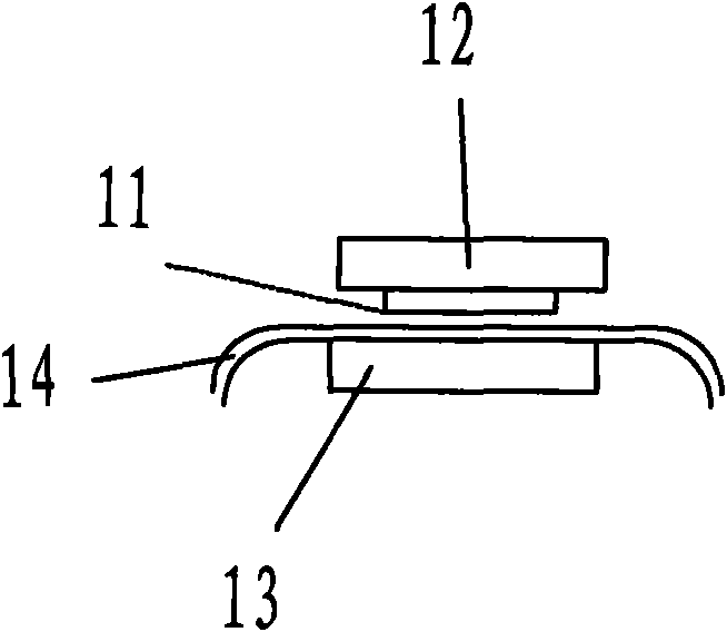
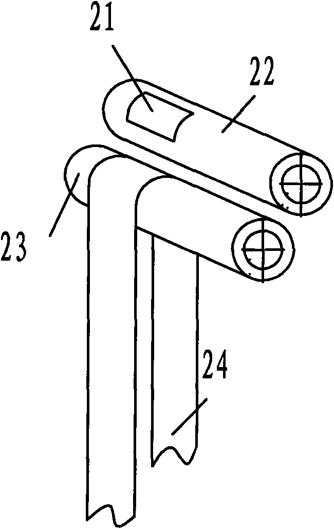
[0021] The main parts and details of a die-cutting machine suitable for drum materials with improved die-cutting tool structure of the present invention: 31. X-direction knife-feeding motor (servo or stepping motor), 31'. Y-direction knife-feeding Motor, 32. Horizontal mechanism (X-direction mechanism), 32'.Y-direction mechanism, 33. Knife rest, 34. Die-cutting tool, 35. Mark detection sensor, 36. Traction motor (servo or stepping motor), 37. Traction roller, 38. Traction pressure wheel, 39. Return roller, 40. Return motor, 41. Backing plate, 42. Coil (die-cut paper), 13. Control system. 44. Knife holder guide rail, 45. Block, 46. go back pressure roller (resistance pressure roller), 47. mark.

[0022] Such as Figure 3-1 As shown, a kind of die-cutting machine suitable for drum materials with an improved die-cutting tool structure ...


PUM


Abstract

The invention discloses a die-cutting cutter structure improved die-cutting machine for wound roll materials, which can solve the technical problems in the prior art that a die-cutting cutter has high cost, long manufacturing period, poor durability, complex machine adjustment, heavy machine, poor die-cutting quality and low die-cutting speed, is not suitable for small scale production and the like. The die-cutting machine comprises a machine frame, a coiled material tension unit as well as a coiled material traction unit, a mark checking unit and at least one cutting feed unit respectively connected with a control system, wherein the coiled material traction unit controls a coiled material to move forward along the longitudinal direction of the coiled material; the coiled material tension unit controls the coiled material to move backward along the longitudinal direction of the coiled material or provides a Y-direction tension force for the coiled material; the mark checking unit comprises a mark arranged on the coiled material and a mark checking sensor; and the cutting feed unit controls a die-cutting cutter and comprises a guide rail arranged on the machine frame, a tool holder positioned on the guide rail and connected with a cutting feed motor and a cutter arranged on the tool holder.

Description

technical field [0001] The invention relates to a machine for die-cutting creasing or die-cutting, in particular to a die-cutting machine with an improved structure of a die-cutting tool suitable for drum materials. Background technique [0002] Die-cutting machines are usually used in the manufacturing process of paper or similar material products. Die-cutting machines are divided into flat-pressed flat, round-pressed round, flat-pressed round or Round flattened die-cut form. At present, the die-cutting forms of flat pressing and round pressing are commonly used in die-cutting machines. Among them, such as Picture 1-1 and Figure 1-2 The structure shown in the form of flat die-cutting includes a die-cutting plate 11 located below the upper platen 12, and a lower backing plate 13 located below the receiving medium 14. The flat-pressed flat die-cutting relies on the downward punching of the die-cutting plate 11. The characteristics of the flat die-cutting are: there are h...

Claims


Application Information

Patent Timeline
Patent Type & Authority Applications(China)
IPC IPC(8): B26D1/01B26D5/08B26D7/26B26D7/06
Inventor 杜建刚
Owner 杜建刚
Why Eureka
Try Eureka