Expansion method and expansion equipment thereof of thermal shrinkage pipe material with large caliber

A heat-shrinkable tube and large-diameter technology, which is applied to tubular objects, other household appliances, and household appliances, can solve the problems of low production efficiency and slow expansion speed of large-diameter heat-shrinkable tubes, so as to improve production efficiency and reduce pulling Force, the effect of increasing the expansion speed

Active Publication Date: 2009-12-30
SHENZHEN WOER HEAT SHRINKABLE MATERIAL
View PDF2 Cites 10 Cited by
  • Summary
  • Abstract
  • Description
  • Claims
  • Application Information

AI Technical Summary

Problems solved by technology

[0003] In order to overcome the shortcomings of slow expansion speed and low production efficiency of large-diameter heat-shrinkable tubing, the present invention provides a heat-shrinkable tubing expansion method and expansion equipment. The principle is: expansion and retraction are not performed simultaneously, but intermittently The cycle is carried out, that is, the tube is not retracted when expanding, and the tube is not expanded when retracting. Since the tube is not expanded when retracting, the pulling force on the tube when retracting can be greatly reduced. Therefore, by lengthening the length of the expansion mold, it can be greatly improved. Improve expansion speed and improve production efficiency

Method used


Image

  • Expansion method and expansion equipment thereof of thermal shrinkage pipe material with large caliber
  • Expansion method and expansion equipment thereof of thermal shrinkage pipe material with large caliber
  • Expansion method and expansion equipment thereof of thermal shrinkage pipe material with large caliber

Examples


Embodiment Construction

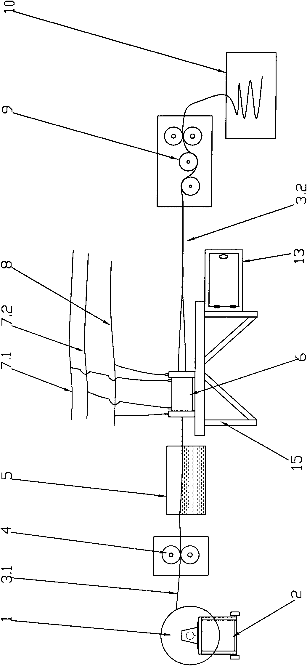
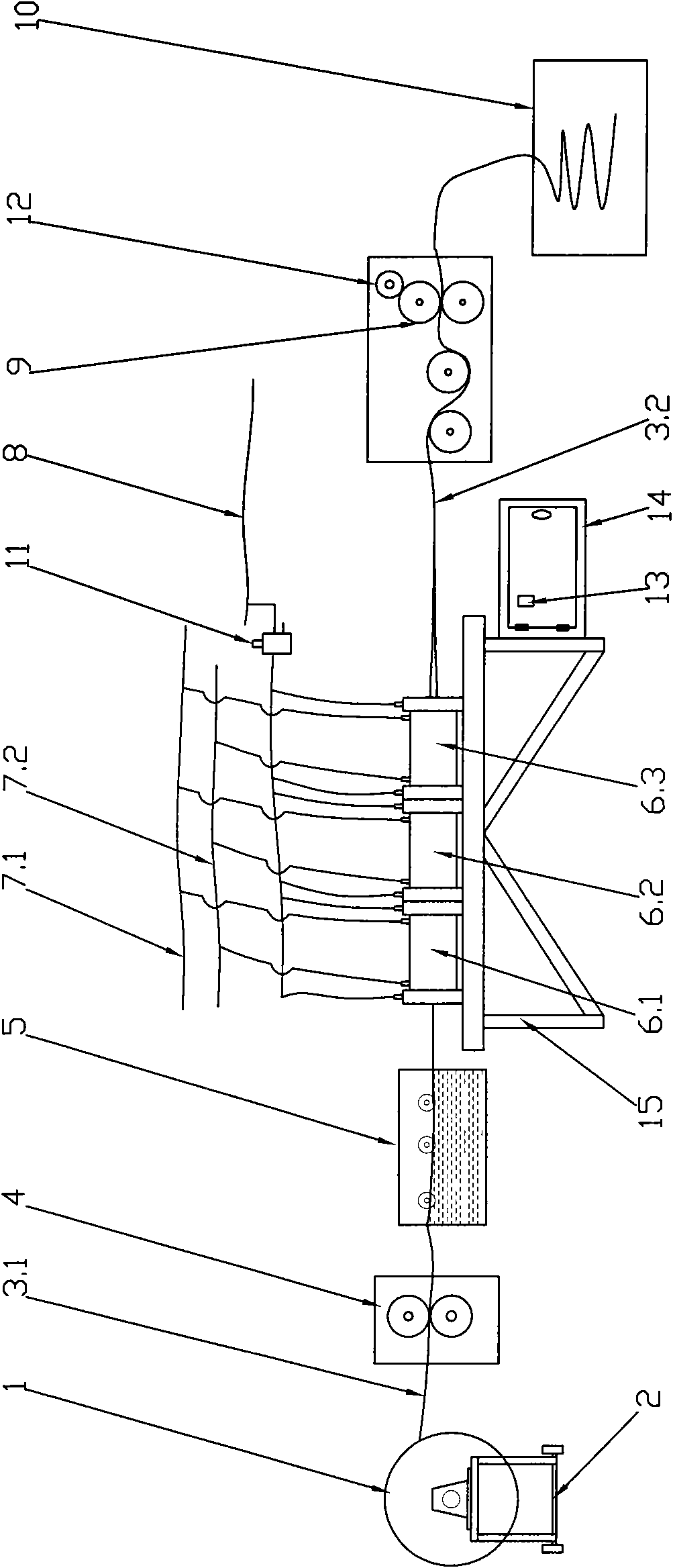
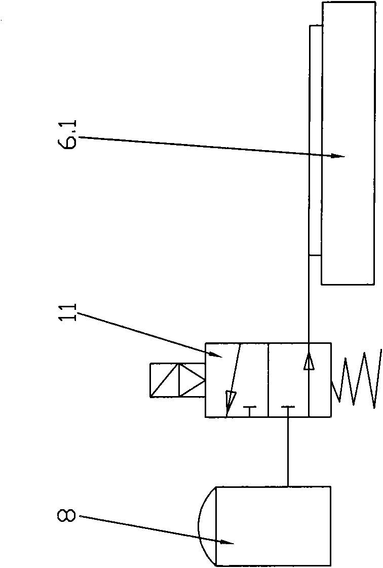
[0013] exist figure 1 It can be seen from the embodiment that in the prior art, the expansion mold 6 is connected to the vacuum system 8 and the cooling circulation system 7.1 and 7.2 respectively, the inner cavity of the mold 6 is kept in a vacuum state and a cooling state, and the tube feeder 9 will heat shrink the tubing 3.1 Send it into the heating oil tank 5 for soaking and heating. Under the action of the tube collector 9, the heated pipe 3.1 enters the expansion mold 6 from one end, expands, cools and shapes in the mold 6, and then is pulled out from the other end of the mold 6 , which is characterized by: in the process of expansion, processes such as expansion and management have been carried out simultaneously and continuously. Because the heat-shrinkable tubing produces pressure on the inner wall of the mold when it expands, causing frictional resistance between the two, the tube retractor 9 must have a certain pulling force when retracting the tube, so as to overco...


PUM


Abstract

The invention relates to an expansion method and expansion equipment thereof of a thermal shrinkage pipe material with large caliber, aiming at overcoming the defects of very low expansion speed and low production efficiency caused by such a way that the existing thermal shrinkage pipe material with large caliber adopts a continuous expansion and continuous pipe shrinkage method during expanding. The invention provides an expansion method of a novel thermal shrinkage pipe material with large caliber and adopts the technical concept that expansion and pipe shrinkage are discontinuously carried out circularly; namely, the pipe shrinkage is not carried out at the time of the expansion and the expansion is not carried out at the time of the pipe shrinkage; pulling force to the pipe material can be greatly reduced at the time of the pipe shrinkage because the expansion is not carried out at the time of the pipe shrinkage, and two problems of cooling moulding and tensile deformation of the pipe material are solved; therefore, the expansion speed and the production efficiency can be enhanced lengthening an expansion mould; and simultaneously, the invention also utilizes the concept to design the corresponding expansion equipment, utilizes a time control switch and an electromagnetic valve to carry out discontinuous air suction and exhaust on the expansion mould, utilizes a stroke measurement control switch to control the pipe shrinkage length and realizes that two procedures of expansion and pipe shrinkage are discontinuously carried out circularly.

Description

technical field [0001] The invention relates to a heat-shrinkable tubing expansion method and its expansion equipment, in particular to a large-diameter heat-shrinkable tubing expansion method and its expansion equipment. Background technique [0002] At present, the principle of the heat-shrinkable tube expansion machine is as follows: the expansion mold is connected to the vacuum system and the cooling circulation system respectively, so that the inner cavity of the mold is kept in a vacuum state and a cool state, and the tube feeder sends the heat-shrinkable tube into the oil tank for soaking and heating. Under the action of the tube collecting machine, the heated tube enters the expansion mold from one end, expands and cools in the mold, and then is pulled out from the other end of the mold. It has been done simultaneously and continuously. Because the heat-shrinkable tubing produces pressure on the inner wall of the mold when it expands, resulting in frictional resista...

Claims


Application Information

Patent Timeline
Patent Type & Authority Applications(China)
IPC IPC(8): B29C57/08B29L23/00
Inventor 何少敦周和平
Owner SHENZHEN WOER HEAT SHRINKABLE MATERIAL
Why Eureka
Try Eureka