Directly-pushing connecting pipe joint

A technology for connecting pipes and elastic openings, applied in the direction of pipe/pipe joint/pipe fitting, sleeve/socket connection, passing components, etc., can solve problems such as difficulties, rising material costs and processing costs, waste materials, etc., and achieve convenient processing and formation , Saving raw materials and reducing costs

Active Publication Date: 2009-12-30
佛山市立联吉管业科技有限公司
View PDF0 Cites 13 Cited by
  • Summary
  • Abstract
  • Description
  • Claims
  • Application Information

AI Technical Summary

Problems solved by technology

[0005] First of all, since the groove for installing the sealing rubber ring is opened on the wall of the through hole of the joint body, there is a gap between the innermost end of the horn hole, see figure 1 In this way, many problems are caused in the manufacture of the joint body: if lathes are used to make grooves and horn holes on the joint body, the wall thickness of the joint body will be greatly increased, and the cost of materials and processing costs will increase. It will increase by about 4 times, and the pipe joints need to be mass-produced
[0006] Second, if the joint body is made by the profiling cold expansion tube method, since the distance between the groove of the sealing rubber ring and the horn hole is generally very small (it is too large to waste material), it is necessary to make the joint body in a very short length. It is very difficult for the joint body to produce such a large curvature change, and the cold expansion tube can only be molded twice, which also increases the processing cost
[0007] In addition, the width of the groove of the sealing rubber ring has higher requirements, because if the groove width is wider than the sealing rubber ring, the sealing rubber rin

Method used


Image

  • Directly-pushing connecting pipe joint
  • Directly-pushing connecting pipe joint
  • Directly-pushing connecting pipe joint

Examples


Embodiment Construction

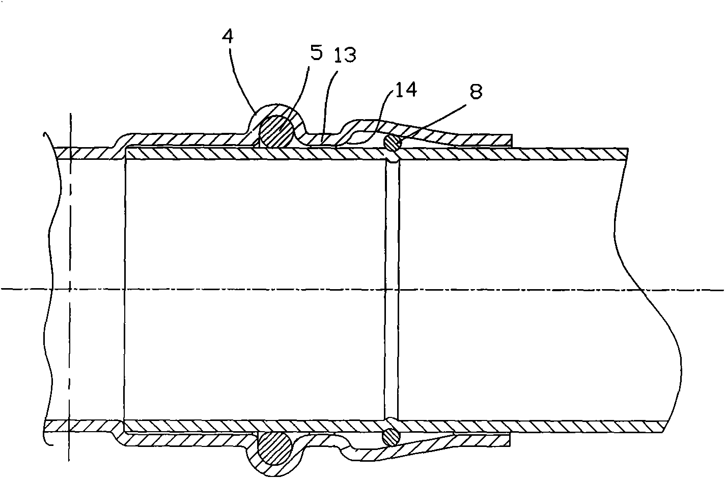
[0035] Such as figure 1 Shown is the closest structural cross-sectional view of the prior art. There is a gap 13 between the groove of the sealing rubber ring in the through hole of the joint body and the innermost end of the horn hole. To be thicker, or to increase the pipe processing costs for a second time.

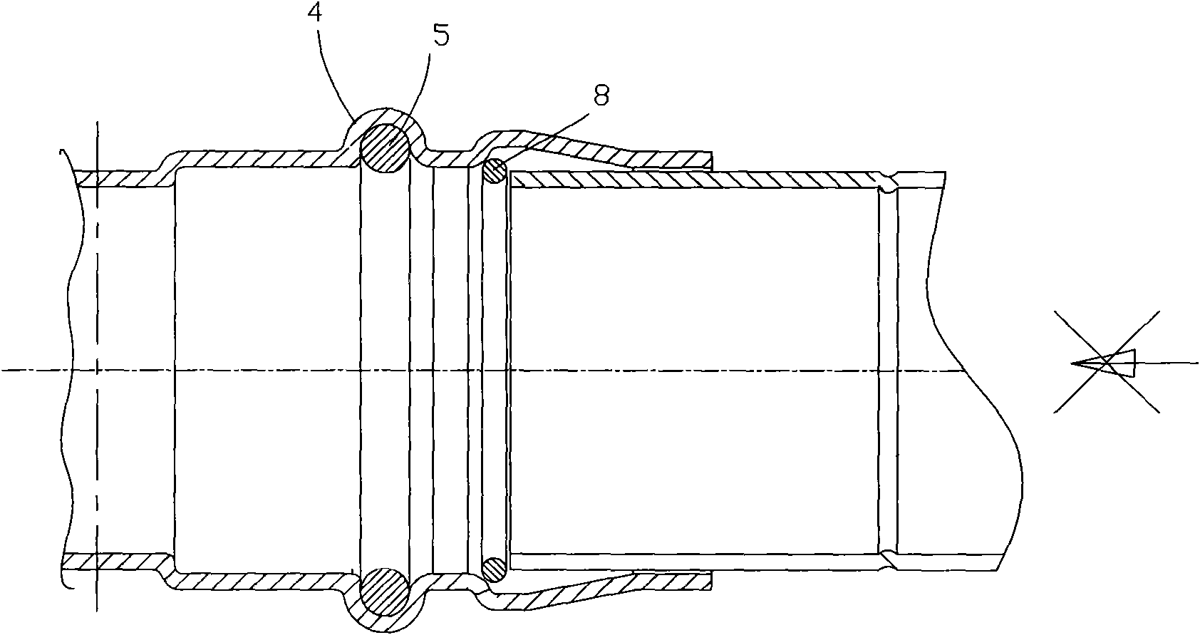
[0036] In addition, see figure 2 , Which is figure 1 When the pipe joint is inserted by the connecting pipe, the snap ring is deadlocked. Because the big end of the horn hole is always closed at the end, it must be over-connected with the through hole that adapts to the outer diameter of the connected pipe. This is bound to have an excessive arc. When the radius of the excessive arc is larger than the pitch diameter of the circular elastic snap ring, it will happen that the elastic snap ring will die on the excessive circle of the large end of the horn hole when the connected pipe is inserted. In the arc position and cannot be expanded, the connected tube cannot be inse...


PUM


Abstract

The invention relates to a directly-pushing connecting pipe joint comprising a joint body (3) with a through hole (2) for the insertion of a connecting pipe (1) to be connected. A sealing rubber ring (5) forming a water-tight seal with the body of the connecting pipe (1) to be connected is mounted in the through hole (2), stepped holes respectively having a large interior and a small exterior are respectively arranged at both ends of the through hole (2); the outer small hole is a sealing section (6) and has an inside diameter adaptive to the outer diameter of the connecting pipe (1) to be connected; the inner large hole is a horn hole (7) with a large mouth facing inward; a gap is formed between the inner wall of the horn hole (7) and the connecting pipe (1) to be connected; the sealing rubber ring (5) is mounted at the innermost end of the gap which is also provided with an elastic open clasp ring (8); and a circular clasp ring groove (9) corresponding to the elastic open clasp ring (8) is arranged outside the connecting pipe (1) to be connected. The groove in the joint body (2) of the connecting pipe (1) is directly arranged on the inner end wall of the horn hole (7) so that the joint body avoids generating great curvature change in a very short time and can be made by once profiling a cold expanding pipe to save raw materials and decrease the cost.

Description

Technical field [0001] The invention relates to a pipe connector, in particular to a direct push connection pipe joint. Background technique [0002] The pipe connection is generally through a pipe joint, and the connected pipe and the joint are generally connected by a thread, and there are also connection structures that use an internal tooth split snap ring. There is also a direct-push connection structure that uses a combination of an elastic opening snap ring and a conical surface, and the connected pipe can be directly pushed into the joint body for connection, but is limited by the conical surface and the elastic opening snap ring and cannot be pulled out. [0003] A conventional pipe joint includes a joint body with a through hole for a connected pipe to be inserted into, a groove is opened in the through hole, and a sealing rubber ring that forms a water seal with the pipe body to be connected is provided at both ends of the through hole. For the horn hole with a large m...

Claims


Application Information

Patent Timeline
IPC IPC(8): F16L21/02F16L37/088
CPCF16L37/088
Inventor 伍婧绫
Owner 佛山市立联吉管业科技有限公司
Why Eureka
Try Eureka