Method for carrying out streamline-form thickening on airfoil shape tailing edge

A streamlined, airfoil-shaped technology, applied to wind turbines at right angles to the wind direction, wind turbines in line with the wind direction, and greenhouse gas reduction, can solve problems such as ambiguity and practical implementation difficulties, and achieve late stall, Good social value and economic value, the effect of improving the lift coefficient

Inactive Publication Date: 2009-12-30
CHONGQING UNIV
View PDF1 Cites 15 Cited by
  • Summary
  • Abstract
  • Description
  • Claims
  • Application Information

AI Technical Summary

Problems solved by technology

However, since it did not propose a thickening scheme for the trailing edge of the system, it is not clear what thickening methods should be used for different airfoils, and there are great difficulties in actual implementation.

Method used


Image

  • Method for carrying out streamline-form thickening on airfoil shape tailing edge
  • Method for carrying out streamline-form thickening on airfoil shape tailing edge
  • Method for carrying out streamline-form thickening on airfoil shape tailing edge

Examples


Embodiment 1

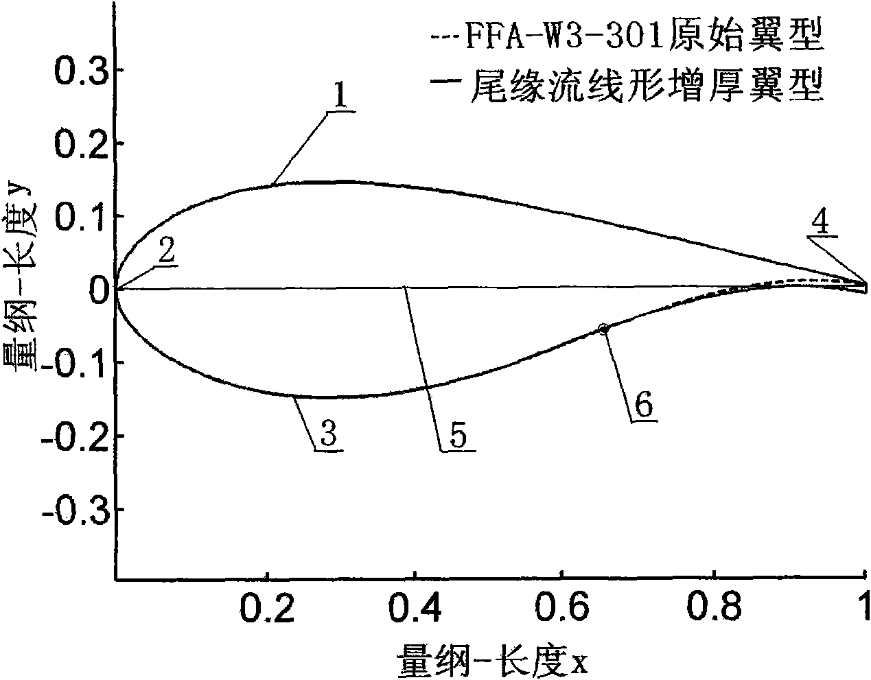
[0047] The FFA-W3-301 airfoil is selected as the original airfoil, and the trailing edge is streamlined and thickened according to the original airfoil. In the design process, the three parameters (τ, κ, ξ) in the control equation are selected as the control variables, and the average lift-to-drag ratio under the angle of attack of 5°-10° is used as the objective function, according to the genetic algorithm mentioned above The model is optimized. From the FFA-W3-301 airfoil as the original airfoil, the following figure 1 The streamlined thickened trailing edge airfoil shown.

[0048] The three parameters obtained from the FFA-W3-301 airfoil optimized for the original airfoil are:

[0049] (τ, κ, ξ) = (0.012, 0.68, 1.12)

[0050] That is, the thickness of the streamlined thickened trailing edge is 1.2% of the chord length, and the thickening starting point is at 68% of the chord length direction.

[0051] refer to figure 1 , the dotted line is the original airfoil of FFA-W...

Embodiment 2

[0053] The NACA63430 airfoil is selected as the original airfoil, and the trailing edge is streamlined and thickened according to the original airfoil. In the design process, the three parameters (τ, κ, ξ) in the control equation are selected as the control variables, and the average lift-to-drag ratio under the angle of attack of 5°-10° is used as the objective function, according to the genetic algorithm mentioned above The model is optimized. From the NACA63430 airfoil as the original airfoil respectively obtained as follows Figure 4 The streamlined thickened trailing edge airfoil shown.

[0054] The three parameters obtained by optimizing the original airfoil from the NACA63430 airfoil are:

[0055] (τ, κ, ξ) = (0.02, 0.85, 1.15)

[0056] That is, the thickness of the streamlined thickened trailing edge is 2% of the chord length, and the thickening starting point is at 85% of the chord length direction.

[0057] refer to Figure 4 , the dotted line is the original ai...


PUM


Abstract

The invention discloses a method for carrying out streamline-form thickening on airfoil shape tailing edge, which is mainly applied to the improvement field of wind machine blades; the reformed airfoil shape designed by the method has better pneumatic performance than the original airfoil shape; in the proper functioning angle of attack range, not only the lift coefficient of the improved the airfoil shape is increased, but also the control method provided by the invention guarantees the streamline-form characteristics of the airfoil shape pressuring surface, thereby the resistance coefficient of the airfoil shape is very small, the airfoil shape has higher lift drag ratio, simultaneously, is later in stall, and has good social and economic values.

Description

technical field [0001] The invention relates to the field of improvement of wind turbine blades, in particular to a method for streamlined thickening of the trailing edge of an airfoil. Background technique [0002] Wind energy, as a renewable and clean energy, has been widely valued by countries all over the world. Wind power generation is the main way to utilize wind energy, but the power generation efficiency and high cost of wind turbines have caused difficulties for the development of wind power generation. The power of the current wind turbine rotor is increased mainly by increasing the length of its blades. However, when the length of the blade increases to a certain extent, the mass of the wind rotor will also increase greatly, which will cause the load of the entire wind turbine to exceed the rated range and increase its manufacturing cost. The performance of the cross-section airfoil of the wind turbine blade has a decisive influence on the aerodynamic performanc...

Claims


Application Information

Patent Timeline
Patent Type & Authority Applications(China)
IPC IPC(8): G06F17/50F03D1/06F03D3/06F03D11/00F03D80/00
CPCY02E10/74Y02E10/72Y02E10/721
Inventor 陈进陆群峰程江涛
Owner CHONGQING UNIV
Why Eureka
Try Eureka